
When disc brakes first began replacing four wheel drum setups on American passenger cars in the mid 1960s, engineers installed them exclusively on the front axle where kinetic energy concentrates during a stop. Understanding why modern four wheel disc systems still divide stopping workloads unequally between front and rear brake pads helps new owners manage maintenance costs and vehicle safety. Rather than treating every corner of the chassis as identical, smart drivers learn how weight transfer, caliper mechanics, and electronic brake distribution affect wear rates across each axle.
Why Front and Rear Brake Pads Handle Different Workloads
The Physics of Weight Transfer and Kinetic Energy
Think about what happens to everyone inside the cabin when you press firmly on the brake pedal approaching a red light. Your body immediately leans forward against the seatbelt strap as the vehicle decelerates. That exact same physical momentum applies to the entire mass of your car. Because the center of gravity sits above the pavement, rapid deceleration pitches the weight of the engine, transmission, and chassis forward onto the front suspension.
As this mass shifts toward the nose, it presses the front tires harder into the asphalt while unweighting the rear tires. Increased downward force gives the front tires tremendous mechanical grip, whereas the lighter rear tires lose traction more easily and risk locking up if overbraked. Consequently, front and rear brake pads experience vastly different mechanical demands during everyday driving. On most passenger sedans, crossovers, and pickup trucks, the front braking components absorb up to 75 percent of the total kinetic energy required to bring the vehicle to a halt. Knowing how this forward pitch shapes component longevity is the foundation of planning a timely brake pad replacement before worn linings damage expensive rotors.
Component Sizing and Thermal Dissipation
Because brakes work by converting kinetic motion into thermal energy through friction, absorbing three quarters of the stopping force generates immense heat at the front hubs. Open your wheel wells or peek through the spokes of almost any modern vehicle, and you will immediately spot the physical sizing disparity engineered to manage this heat. Automotive engineers equip the front axle with noticeably wider, longer friction linings that sweep across a much larger surface area.
Front brake rotors also feature larger outer diameters and thicker cross sections than their rear counterparts. More importantly, nearly all front rotors are internally vented, meaning they consist of two circular iron friction faces separated by hollow cooling vanes that pump hot air outward as the wheel spins. Rear rotors on everyday commuters are frequently smaller in diameter, thinner, and sometimes cast as a single solid piece of iron without cooling vents. New owners shopping for our top picks for first time buyers can easily spot this size difference during a pre purchase walkaround, confirming that the heavy thermal lifting belongs to the front end.
Hydraulic Bias Versus Electronic Brake Force Distribution
For decades, vehicles relied on a mechanical hydraulic proportioning valve to regulate pressure between the front and rear fluid lines. These valves physically restricted hydraulic pressure to the rear wheels during heavy stops so the rear tires would not lock up and spin the car out of control. Under traditional hydraulic bias, front brake pads routinely wore out two to three times faster than the rear set.
Modern computer controlled braking has rewritten that predictable wear ratio. As detailed in a technical brake balance analysis from AA1Car, electronic brake force distribution and dynamic stability control systems actively modulate hydraulic valves to engage the rear brakes early during light pedal applications. Applying slight rear drag first keeps the chassis flat, prevents annoying front end nose dive in stop and go traffic, and stabilizes the vehicle through corners. Because the computer pulses the rear calipers constantly during gentle commuting, many owners of newer vehicles are shocked to discover their smaller rear pads wearing down faster than their massive front pads. Front and rear braking systems function as a dynamic team where physics and software constantly trade duties rather than operating as four identical corners.
Structural Differences in Caliper Designs and Parking Brake Hardware
Floating Calipers Versus Fixed Multi Piston Designs
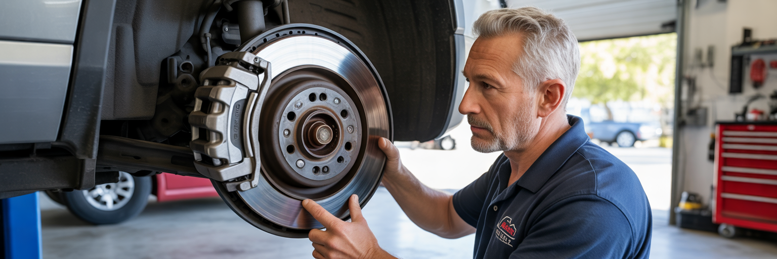
Stepping behind the wheel spokes reveals that calipers themselves vary widely in how they clamp the friction pads against the spinning rotor. The vast majority of everyday passenger cars and light trucks utilize floating calipers on both axles. A floating caliper houses one or two hydraulic pistons on the inboard side only. When hydraulic fluid pushes the piston outward against the inner pad, the entire outer caliper housing slides inward along steel pins, pulling the outer pad tight against the opposite face of the rotor like a C clamp.
High performance sports cars, heavy towing rigs, and luxury sedans often upgrade the front axle to fixed multi piston calipers. A fixed caliper bolts rigidly to the steering knuckle and never slides. Instead, it uses pairs of opposing pistons on both the inboard and outboard sides of the rotor to squeeze both pads simultaneously with rigid precision. Even on vehicles equipped with massive four or six piston fixed calipers up front, engineers frequently retain a simpler single piston floating caliper on the rear axle where peak clamping force is lower and packaging space is tight.
Three Rear Parking Brake Configurations in the US Market
Despite handling less raw stopping energy than the front units, a rear parking brake caliper or hub assembly is often far more mechanically complex. Federal safety standards require a secondary parking brake system capable of holding a parked vehicle stationary without relying on hydraulic fluid pressure, which can bleed down or leak over time. In the United States market, engineers solve this requirement using one of three distinct rear configurations.
First is the traditional drum in hat system. Here, the rear caliper functions strictly as a simple hydraulic disc brake, while the deep center hub of the rear rotor acts as a miniature brake drum hiding a separate set of curved friction shoes actuated by a steel pull cable. Second is the mechanical screw type integrated caliper, where pulling the handbrake lever tugs a steel cable attached to a spring loaded arm on the back of the caliper body, rotating a threaded internal spindle that mechanically pushes the main caliper piston outward. Third is the modern electronic parking brake system, popularized early on by several vehicles featured in our guide to used German cars, which mounts a high torque electric stepper motor directly onto the rear caliper housing to drive an internal ball screw assembly at the touch of a console button.
Retracting Pistons Safely Without Ruining Rear Calipers
Understanding which rear caliper style sits on your axle is critical before you ever pick up a wrench. On a standard front caliper or a rear caliper paired with a drum in hat parking brake, the hollow piston simply slides straight back into its bore using a basic compression tool or C clamp when you install thick new pads. Attempting to force a screw type or motorized rear piston straight back with a C clamp will crush the internal threaded spindle or shatter the plastic planetary gears inside the electric stepper motor, turning a routine pad swap into an expensive caliper replacement.
Mechanical screw type rear calipers feature notches cut into the face of the piston. These require a slotted wind back cube tool or specialized ratcheting brake press that rotates the piston clockwise while applying inward pressure, threading it neatly back down its internal screw shaft. For electronic parking brake calipers, you must first command the electric motor to unwind its internal screw before touching the piston. Many vehicles allow you to trigger a maintenance retraction mode through a specific sequence of ignition, pedal, and parking switch presses on the dashboard, while others require plugging an OBD II diagnostic scan tool into the steering column port to wind the stepper motors back electronically. Once the motor whirs to a complete stop, the hydraulic piston can then be pressed straight back by hand.
Before ordering parts or lifting your car, take sixty seconds to crouch behind the rear bumper with a flashlight and inspect the inboard side of the rear hub. If you see a braided steel cable hooked to a spring lever directly on the caliper body, you will need a wind back rotation tool. If you spot a plastic electrical wiring harness plugged into a black plastic motor housing bolted to the back of the caliper, prepare for an electronic service mode retraction. If the caliper has only a single rubber hydraulic hose and a rubber oblong inspection plug sits on the backing plate behind the rotor, you are looking at a drum in hat setup whose caliper piston pushes straight back just like the fronts.
Decoding Pad Wear Patterns to Spot Mechanical Issues Early
Normal Lining Wear Versus Minimum Thickness Specifications
Every set of brake pads tells a clear mechanical story about the health of your hydraulic system and mounting hardware. When you unbox a fresh set of passenger car brake pads, the friction lining bonded to the steel backing plate typically measures between 10 and 12 millimeters thick. Under healthy operating conditions, all four pads on a single axle should wear down steadily and flatly across their entire friction face as miles accumulate.
Automotive manufacturers and state safety inspectors establish minimum friction lining thickness specifications between 2 and 3 millimeters. Once the lining wears down to that threshold, the thin remaining layer of material loses its ability to insulate the brake fluid from extreme heat, and the steel backing plate risks grinding directly into the cast iron rotor. Most pads include a small spring steel tang riveted to the backing plate that contacts the rotor at around 2 millimeters, emitting a high pitched metallic chirp while the wheel rolls to alert the driver. However, discovering uneven brake pad wear during a routine tire rotation reveals that a mechanical bind is starving one corner of proper movement long before the wear sensor ever chirps.
Inner Versus Outer Pad Discrepancies on Floating Calipers
When inspecting a floating caliper setup, comparing the thickness of the inboard pad against the outboard pad on the exact same wheel is your best diagnostic test. It is entirely normal for the inner pad to wear roughly 1 millimeter thinner than the outer pad over a full service life because the hydraulic piston pushes directly against the inner backing plate milliseconds before the caliper housing slides inward to engage the outer pad. Anything beyond that tiny variance points to a mechanical fault.
As outlined in technical inspection standards from Brake and Front End, a thickness difference exceeding 2 to 3 millimeters between the inner and outer linings indicates a failure in the sliding mechanism. If the inner pad is worn down to bare metal while the outer pad looks nearly new, the hydraulic piston is extending normally, but seized floating caliper guide pins are preventing the outer housing from sliding inward to share the clamping load. Conversely, if the outer pad is completely worn away while the inner pad retains plenty of thickness, the caliper body slid inward during braking but failed to relax and release pressure after you lifted your foot off the pedal, keeping the outer lining dragged tightly against the spinning rotor at highway speeds.
Tapered Linings, Grooves, and Bracket Rust Jacking
Laying a removed brake pad flat on your workbench and sighting down its edge reveals whether the lining wore parallel to the steel backing plate. If one end of the pad is noticeably thinner than the other in a wedge or tapered shape, the pad is cocking sideways inside the caliper bracket under braking torque. In northern climates, this taper almost always stems from rust jacking, a phenomenon where iron oxide builds up on the cast iron caliper bracket underneath the stainless steel mounting clips, swelling upward and pinching one ear of the brake pad tightly so only the opposite end can move toward the rotor.
Inspecting the face of the friction material is equally revealing. Deep circular grooves cut into the pad face mirror matching ridges scored into an aging rotor, often caused by rocks trapped behind the dust shield or metallic debris embedded in low quality linings. Furthermore, if the pad surface looks glossy and mirror smooth with tiny heat cracks around the edges, the friction resins have overheated and crystallized due to a dragging caliper piston or riding the brakes down a steep mountain grade. Treating your old pads as forensic evidence ensures you fix the root mechanical cause rather than slapping new linings into a faulty bracket.
| Observed Wear Pattern | Primary Mechanical Cause | Affected Component | Required Corrective Action |
|---|---|---|---|
| Inner pad worn 3mm+ thinner than outer pad | Caliper housing fails to slide inward during braking | Seized guide pins or dry slide bores | Clean slide bores, replace pins and boots, apply silicone grease |
| Outer pad worn significantly thinner than inner pad | Caliper body fails to relax after pedal release | Binding caliper bracket or corroded pad ears | File bracket rust scale, replace abutment clips, verify piston retraction |
| Tapered or wedge-shaped lining from top to bottom | Pad cocks sideways under braking torque | Rust jacking under clips or warped caliper bracket | Wire-brush bracket channels, install new clips, replace bracket if bent |
| Cracked, glazed, or crumbling friction surface | Extreme thermal overload and resin overheating | Undersized pad compound or dragging caliper piston | Verify caliper piston moves freely, upgrade to higher temp compound |
This diagnostic table pairs specific visual wear anomalies measured in the garage with their exact mechanical root causes, helping owners fix the underlying hardware failure rather than simply hanging new pads that will wear unevenly again.
Choosing Friction Materials for Front and Rear Applications
Ceramic, Semi Metallic, and Organic Compounds Compared
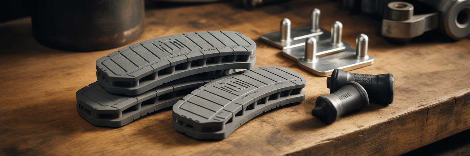
Walking up to the parts counter or browsing online catalogs presents new owners with three primary friction chemical formulations: non asbestos organic, semi metallic, and ceramic. Non asbestos organic pads bind fibers like glass, rubber, and Kevlar together in high temperature resins. They feel soft and progressive underfoot and barely wear down iron rotors, though they shed dark dust and lose friction rapidly when pushed hard on steep hills.
Semi metallic pads mix between 30 and 65 percent finely powdered steel, copper, and iron wool into the friction matrix. All that metal makes them exceptional thermal conductors that pull heat away from the rotor interface and resist brake fade under extreme loads, though they wear rotors faster, produce heavy black metallic dust, and occasionally squeal on cold mornings. Ceramic brake pads combine dense kiln fired ceramic compounds with fine copper or synthetic fibers. They operate almost silently, generate very fine light gray dust that rarely stains alloy wheels, and deliver long pad and rotor life across normal driving temperatures.
Matching Pad Compounds to Vehicle Weight and Towing Demands
Selecting the right friction compound depends entirely on the mass of your vehicle and the geography you drive through. If you pilot a heavy duty pickup or full size SUV pulling a travel trailer down steep grades like the Eisenhower Pass in Colorado, thermal capacity is everything. Drivers relying on any of the rigs highlighted in our guide to used trucks for towing a camper should install quality semi metallic pads, especially on the front axle, where metallic compounds bite aggressively and resist thermal fade when eight thousand pounds of combined weight pushes down a mountain pass.
Conversely, daily suburban commuters, family sedans, and high mileage city crossovers rarely generate the sustained rotor temperatures needed to overwhelm a ceramic pad. Owners logging thousands of stop and go urban miles in vehicles featured on our list of the best cars for Uber and rideshare drivers benefit tremendously from ceramic linings, which keep pedal modulation smooth for passengers, eliminate embarrassing intersection squeals, and extend replacement intervals.
Why Mixing Friction Profiles Across Axles Disrupts Brake Balance
When servicing only one end of the vehicle, some drivers wonder if they can install aggressive semi metallic performance pads on the front axle while leaving inexpensive organic or ceramic pads on the rear. While engineers occasionally specify slightly different factory compounds front to rear to fine tune pedal feel on heavy trucks, haphazardly mixing aftermarket compounds with wildly different friction coefficients disrupts your car’s engineered brake balance.
Every friction compound has a specific temperature curve where it achieves peak grip. Installing high bite metallic pads up front paired with low friction pads in the rear shifts an even larger percentage of the stopping load onto the front tires during sudden stops. On slick, rain soaked asphalt, this imbalance can cause the front tires to reach their traction limit prematurely, triggering early anti lock braking chatter and confusing electronic stability control algorithms that expect predictable deceleration rates across all four wheel speed sensors. Always match the friction category of your replacement pads to the factory specification or keep both axles within the same compound family.
| Friction Compound | Operating Temperature Tolerance | Cold Pedal Bite and Feel | Rotor Wear and Brake Dust | Ideal Vehicle Application |
|---|---|---|---|---|
| Non-Asbestos Organic (NAO) | Low to moderate heat capacity; prone to fade on long grades | Smooth, progressive initial engagement | Very gentle on rotors; produces moderate dark dust | Light compact sedans and low-speed city commuters |
| Ceramic Formulations | Moderate to high heat stability across daily driving ranges | Consistent, linear pedal response once warmed | Low rotor abrasion; fine, light-colored dust that hides well | Daily drivers, family crossovers, and luxury sedans |
| Semi-Metallic (30% to 65% Metal) | High thermal capacity; resists fade under heavy loads | Immediate, firm initial bite even in freezing weather | Higher rotor wear; generates heavy black metallic dust | Heavy-duty trucks, towing SUVs, and performance cars |
Data reflects industry friction testing standards comparing thermal fade thresholds, rotor abrasion rates, and cold friction coefficients across standard aftermarket street compounds sold in North America. Matching your pad selection to your actual gross vehicle weight and daily terrain keeps your braking responsive without wasting money on noisy racing compounds.
Why Replacing Hardware Clips and Boots Is Mandatory
Environmental Stress, Road Salt, and Thermal Cycling
New DIY mechanics often open a box of replacement brake pads, pull out the four friction linings, and toss the small plastic bag of shiny metal clips and rubber boots straight into the trash because the old ones still sit on the bracket. Skipping those small hardware pieces is the single fastest way to ruin a fresh brake job. Underneath your fenders, brake assemblies endure one of the harshest operating environments on the entire automobile.
During a winter commute across Snow Belt states like Michigan, Ohio, or Pennsylvania, caliper brackets are blasted with liquid calcium chloride, rock salt, gritty slush, and abrasive iron dust while sitting at sub zero temperatures. Minutes later, a firm highway stop heats those exact same metal brackets to several hundred degrees. Repeated extreme thermal cycling causes thin spring steel clips to lose their tension and fatigues rubber seals until they turn hard and brittle.
How Stainless Steel Abutment Clips and Rubber Boots Protect Movement
Each piece in that hardware kit serves a vital mechanical role. The shiny stainless steel abutment clips snap tightly into machined channels on the cast iron caliper mounting bracket. Because cast iron rusts rapidly and creates a rough, pitted surface, these stainless clips provide a slick, corrosion resistant railway track for the stamped steel ears of the brake pads to glide across. They also feature tiny spring tabs that hold the pads gently away from the rotor when your foot is off the pedal, preventing constant drag and metallic rattling over bumps.
Meanwhile, the accordion style rubber guide pin boots seal the precision machined slide bores inside the caliper bracket against water intrusion. Many caliper designs also fit a tiny rubber dampener bushing around the tip of one guide pin to absorb low frequency vibrations. If an aging rubber boot develops a microscopic pinhole tear from road debris or clumsy pry bar handling, rainwater wicked inside the bore will emulsify the grease and rust the steel pin solid to the cast iron bracket within a single season. Consistent attention to these hidden protective seals is a primary reason highlighted in our analysis of why some high mileage cars age better than others over decades of daily use.
Proper Brake Grease Application and Contamination Warnings
Installing fresh hardware requires pairing those clean metal and rubber parts with the correct synthetic brake lubricant. Never reach for a tub of standard petroleum based wheel bearing or chassis grease during a brake service. Petroleum distillates chemically attack EPDM rubber boots and pin bushings, causing the rubber to swell up like a sponge and lock the guide pin tightly inside its bore. Always use a dedicated high temperature pure silicone paste or synthetic ceramic brake lubricant applied strictly to the correct mechanical interfaces:
- Coat the smooth steel shafts of the floating caliper guide pins and pack a small dab inside the rubber accordion boots to keep moisture out of the slide bores.
- Brush a thin film of high temperature paste onto the raw cast iron bracket channels after wire brushing away rust scale, right before snapping the new stainless steel abutment clips into place, to block future rust jacking underneath the clips.
- Apply a light smear of brake lubricant onto the metal backing plate where the caliper piston face and outer caliper fingers press against the pad shim to dampen high frequency squeals.
- Dab a tiny amount of lubricant onto the outer metal edges of the brake pad ears where they slide inside the stainless abutment clips, ensuring zero grease ever touches the friction material or rotor face.
- Keep the swept friction surfaces of the rotor, the pad lining face, and the dry rubber exterior of the dust boots completely free of any grease, oil, or greasy fingerprints.
Taking fifteen extra minutes to wire brush the bracket channels, snap in fresh stainless steel clips, verify supple rubber boots, and lubricate the sliding pins guarantees your new pads will glide effortlessly for their entire service life.
Planning an Axle by Axle Replacement Without Guessing
Why Brakes Are Serviced in Matched Axle Pairs
When a mechanic or inspection report tells you a single brake pad is worn down, a golden rule of automotive safety applies: brake pads and rotors must always be replaced in matched axle pairs. You never replace the pads on just the front left wheel while leaving old pads on the front right wheel. Doing so creates unequal clamping friction between the left and right tires, which will violently yank the steering wheel toward the side with the fresher grip during an emergency highway stop.
However, servicing brakes in matched axle pairs does not mean you must replace all four corners of the vehicle at the exact same time. Because front and rear systems handle different energy loads and wear at independent speeds, planning an axle brake replacement is the smartest mechanical and financial approach for vehicle owners. Knowing when to replace brake pads on the front axle independently of the rear axle saves you hundreds of dollars in premature parts and labor while keeping your stopping performance completely balanced side to side.
How to Inspect Inner and Outer Linings and Rotor Specifications
Relying on a quick glance through your alloy wheel spokes in a parking lot only shows you the thickness of the outboard brake pad. As we saw earlier, the hidden inboard pad pressed against the hydraulic piston and backing plate often wears faster or suffers from pin seizure out of sight. To perform an accurate inspection, park on level concrete, chock the opposite wheels, lift the axle safely onto rated jack stands, and remove both wheels on that axle.
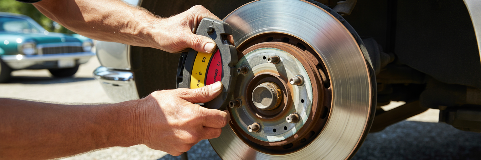
Use an inexpensive color coded metal brake lining gauge to measure both the inner and outer friction pads on each side. Red gauges (2 to 3 millimeters) mean immediate replacement is required, yellow gauges (4 to 5 millimeters) indicate service will be needed within the next few thousand miles, and green gauges (6 millimeters or more) confirm plenty of remaining life. While the wheel is off, inspect the rotor thoroughly. Run your fingernail (once cool) across the swept face to check for deep grooves or a tall rust lip around the outer perimeter edge, look for bluish purple blotches that signal severe overheating, and use an outside micrometer to verify the iron disc remains thicker than the minimum discard specification stamped in millimeters onto the rotor hat or outer rim.
Budgeting Maintenance and Bedding In New Components
Armed with exact millimeter measurements from all eight brake pads, you can take complete control of your maintenance budget. If a service lane advisor recommends an expensive four wheel brake overhaul because your front pads measure 2 millimeters, ask for the exact millimeter readings on the rear pads. If the rear linings still measure 6 or 7 millimeters with smooth, healthy rotors, you can confidently authorize the front axle service today and schedule the rear axle replacement a year or two down the road when those pads actually reach the end of their service life.
Once a new set of pads and rotors is installed on either axle, the job is not finished until you properly seat the hydraulics and bed in the friction material. Follow this exact verification and break in sequence before returning to normal traffic:
- Before starting the engine or shifting the transmission out of park, pump the brake pedal slowly and firmly five to ten times until the pedal transitions from sinking to the floor to feeling rock solid underfoot, which pushes the retracted caliper pistons back out against the new backing plates.
- Pop the hood and inspect the translucent brake fluid reservoir on the master cylinder, confirming the fluid level sits between the minimum and maximum marks and has not overflowed from retracting the caliper pistons.
- Drive slowly out of your driveway onto a quiet, clear road with no traffic behind you and confirm the brakes respond smoothly at low speed without pulling or grinding.
- Accelerate to roughly 40 miles per hour and apply moderate, steady brake pressure to slow the vehicle down to 10 miles per hour without coming to a complete stop, repeating this cycle five times in a row to heat the friction resins gradually.
- Drive at cruising speed for five to ten minutes without touching the brake pedal as much as safely possible, allowing airflow to cool the rotors evenly and cure the microscopic transfer layer of pad material bonded to the iron disc faces.