
Since the introduction of the first front mounted power take off recovery reels on military trucks in the 1940s, self recovery gear has transformed from rudimentary mechanical spools into high torque electric systems capable of pulling several tons out of deep mud. Knowing how to install a winch properly is a foundational skill for any off-roader venturing beyond cell service. Mastering the mechanical and electrical fundamentals of a modern recovery setup ensures your rig can pull itself out of remote backcountry obstacles without compromising your frame or charging system.
Understanding How to Install a Winch and Choose the Right Capacity
Learning how to install a winch begins long before you pick up a ratchet. The most common mistake builders make in the garage is purchasing a recovery unit based on the dry curb weight printed on their driver door jamb sticker. Matching internal motor architecture, gear reduction, and line physics to your actual trail weight ensures the unit will not stall when buried frame deep in thick clay.
Calculating Rated Line Pull and Drum Layering Physics
The baseline industry formula requires multiplying your vehicle weight by 1.5 to determine your minimum rated line pull. However, you must base this math on your fully loaded trail weight rather than factory curb weight or standard gross vehicle weight rating. Once you bolt on plate bumpers, rock sliders, a rooftop tent, spare axle shafts, passengers, and extra fuel cans, your rig is significantly heavier than stock. Base weight varies wildly depending on whether you start with one of the rigs featured in our guide on the best used SUVs for off-roading under $15,000 in 2026 or a heavy full size pickup. Even among midsize trucks, trail mass shifts enough to alter your math, as we detailed in our breakdown of Jeep Gladiator vs Toyota Tacoma off-road capabilities.
Drum layering physics make this 1.5x margin even more critical. Think of the winch drum as a mechanical lever arm. As rope wraps stack on top of one another, the effective diameter of the drum increases, which degrades the mechanical advantage of the gear train. As highlighted in the Warn Industries Basic Guide to Winching, pulling capacity drops by roughly 10 percent with each additional layer of line wound onto the spool, meaning a fully wound drum loses 30 to 40 percent of its rated pulling power. The very first wrap sitting directly against the bare metal drum core is the only layer capable of delivering the maximum advertised pull printed on the housing decal.
Synthetic Rope Versus Steel Cable for 2026 Trail Builds
Choosing a synthetic winch rope setup over traditional braided steel aircraft cable changes both front end handling and trail safety. Swapping out 90 feet of steel wire for modern ultra high molecular weight polyethylene fiber immediately shaves 25 to 30 pounds directly off your front steering axle. Furthermore, synthetic fiber does not store hazardous kinetic energy under tension. If a synthetic line parts under load, it drops toward the dirt rather than whipping back through the windshield like a snapped steel cable.
Still, material selection requires an honest assessment of where you wheel. Steel cable thrives in sharp, abrasive granite environments like the Rubicon Trail or Moab, where dragging a line across jagged rock ledges is unavoidable. Synthetic fibers will fray rapidly if dragged over sharp edges without a sliding abrasion sleeve, and the polymer strands suffer from ultraviolet degradation and retain freezing water during deep winter trail runs. If you wheel primarily in subfreezing ice or use your rig for clearing fallen timber over boulders, steel remains a durable workhorse despite its weight penalty and tendency to develop sharp wire burrs.
Motor Architecture, Gear Ratios, and Ingress Protection
Inside the casing, almost all modern electric recovery winches rely on a three stage planetary gear train to multiply motor torque. The ratio you select dictates a direct mechanical compromise between line retrieval speed and electrical draw. Lower numerical ratios spin the drum faster for quick slack recovery, while deeper ratios around 216:1 or 265:1 multiply torque efficiently without spiking amperage as aggressively. Under a maximum stall load, a 12 volt winch motor frequently pulls 350 to 450 amps, pushing a single lead acid or AGM battery to its thermal limit.
To handle that load, serious trail builders opt for series wound motors rather than permanent magnet motors. Permanent magnet units save manufacturing costs for light ATV or utility trailer duties, but their glued internal magnets lose efficiency when overheated and can crack in subzero weather. Series wound motors use heavy copper field windings that generate superior low end torque and shed heat far more reliably during long pulls. Finally, verify the Ingress Protection rating stamped on the spec sheet. While an IP67 housing survives dust and temporary submersion up to one meter for 30 minutes, an IP68 rated casing is sealed against continuous pressurized water crossings and deep mud bogs.
| Drum Layer / Line Metric | 10,000 lb Winch Effective Pull | 12,000 lb Winch Effective Pull | Synthetic Rope Characteristic | Steel Cable Characteristic |
|---|---|---|---|---|
| Layer 1 (Bare Drum) | 10,000 lbs (100%) | 12,000 lbs (100%) | Requires 5 wraps minimum on drum | Requires 8 wraps minimum on drum |
| Layer 2 | 8,200 lbs (82%) | 9,840 lbs (82%) | Saves 25 to 30 lbs over front axle | Adds significant unsprung front weight |
| Layer 3 | 7,000 lbs (70%) | 8,400 lbs (70%) | Minimal kinetic snap recoil energy | Stores high kinetic energy under tension |
| Layer 4 (Full Drum) | 6,200 lbs (62%) | 7,440 lbs (62%) | Susceptible to rock abrasion and UV rays | High abrasion resistance on sharp granite |
Capacity decay figures reflect standard three stage planetary winch drum diameter increases per wrap, alongside material properties verified across modern off-road recovery tests. Before ordering your unit, weigh your loaded rig at a commercial truck scale, multiply that figure by 1.5, select an IP68 series wound unit if you cross deep water, and match your rope material to your local terrain.
Evaluating Winch Mounting Systems and Structural Requirements
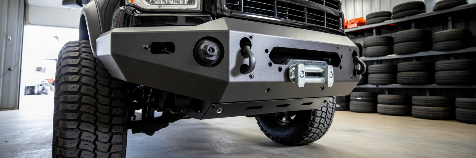
Once you have sized your recovery unit, the next step in this 4×4 winch mounting guide is engineering a structural bridge between the winch feet and your vehicle chassis. A 12,000 pound winch generates enough linear force to rip thin factory bumper brackets straight off the frame rails if the mounting plate geometry is flawed.
Comparing Full Replacement Bumpers, Hidden Cradles, and Universal Plates
Off-roaders generally choose between three structural architectures. Full replacement steel bumpers swap out the entire factory plastic fascia for welded plate or tubular steel that bolts directly to the front frame horns. These offer maximum impact protection against deer strikes and rock ledges, along with welded recovery shackle tabs. However, they carry the highest weight penalty and permanently alter the front profile of your truck.
For daily drivers who prefer a stealthy factory aesthetic, a hidden frame mounted cradle plate tucks neatly inside the hollow cavity behind the original plastic bumper cover. You simply trim a narrow rectangular slot in the lower valence for the fairlead throat. Factory bumper depth and frame horn access vary widely across modern platforms, a design contrast we explored in our comparison of the Ford Bronco vs Toyota Land Cruiser. The third option is a universal two inch receiver hitch cradle. While receiver cradles let you move a single winch between the front and rear hitches or leave it in the garage during the workweek, the overhanging cradle kills your front approach angle on steep trail ledges and can bind inside the receiver tube during off camber side pulls.
Plate Thickness Standards and Foot-Forward Versus Feet-Down Physics
Regardless of which style you prefer, the steel cradle surface where the winch bolts down must be fabricated from at least 6mm (roughly 1/4 inch) thick cold rolled or hot rolled steel. During an angled pull where the line exits the fairlead at 30 degrees, immense twisting forces attempt to parallelogram the winch body. Anything thinner than 6mm will flex under load. When the mounting plate bows even a fraction of an inch, the aluminum end housings twist out of alignment, snapping the upper tie rods and binding the rotating drum tightly against the gearbox casing.
Pay equally close attention to mounting bolt orientation. Most traditional winches are engineered for feet down mounting, where the four bolts pass vertically through the bottom of the cradle plate. Under load, the bolts sit in horizontal shear while the base of the winch presses down against the flat tray. Conversely, many heavy duty steel bumpers use a foot forward mounting face, where the winch rotates 90 degrees forward so its feet bolt directly against the vertical front wall of the bumper. Foot forward mounting is structurally superior because it places the bolts in direct tension and compresses the winch base squarely against the steel plate behind the fairlead. However, you must never mount a standard feet down winch into a foot forward bumper unless the manufacturer explicitly rates the cast feet for vertical compression or provides heavy gusset brackets, as rotational leverage can snap unreinforced cast aluminum legs.
Managing Front Suspension Load, Approach Angles, and Radiator Airflow
Hanging 80 to 160 pounds of steel plate and copper windings three feet ahead of the front axle centerline acts as a long lever arm on your front suspension. On independent front suspension trucks and coil sprung solid axle rigs alike, this cantilevered mass immediately compresses the front struts or coils by half an inch to a full inch. That static sag reduces upward suspension travel, increases nose dive under hard braking, and alters your caster alignment angles. If you pair a full steel bumper with a heavy winch, upgrading to higher spring rate coil springs, adding a heavy duty leaf pack, or adjusting your torsion bars is essential to restore factory ride height and shock damping control.
Additionally, inspect how the mounted assembly interacts with your cooling stack. Sitting a tall external solenoid winch directly in front of the grille blocks ram air flow to the radiator, air conditioning condenser, and transmission oil cooler, which can push coolant temperatures into the danger zone on slow summer climbs.
| Mounting System | Typical Added Weight | Approach Angle Impact | Radiator Airflow Restriction | Best Vehicle Application |
|---|---|---|---|---|
| Full Steel Replacement Bumper | 110 to 160 lbs (with winch) | Improves clearance at frame corners | Moderate to high if external housing sits tall | Dedicated rock crawlers and heavy overland trucks |
| Hidden Frame-Mounted Cradle | 75 to 95 lbs (with winch) | Retains factory bumper overhang geometry | Low when mounted inside lower fascia cavity | Daily driven SUVs and midsize trucks keeping OEM look |
| 2-Inch Receiver Hitch Cradle | 85 to 110 lbs (removable) | Severely reduces clearance when attached | Zero when stored in cargo bed | Multi-vehicle fleets or occasional trail support rigs |
Weight and geometry comparisons assume a standard 10,000 pound capacity winch paired with a 6mm steel cradle plate. Selecting a mounting system that balances approach clearance, radiator airflow, and 6mm plate rigidity prevents structural failure when you are miles from pavement.
Gathering Essential Tools, Hardware, and Electrical Supplies
Nothing derails a Saturday driveway build faster than realizing your factory frame bolts are two threads too short or your socket wrench cannot fit inside a recessed bumper cutout. Staging the proper metallurgical fasteners, matching fairlead hardware, and high amperage electrical protection before unbolting your grille ensures a smooth installation.
Fastener Metallurgy and Fairlead Compatibility Rules
Never substitute standard hardware store bolts if you drop or misplace one of the fasteners included in your winch box. Every bolt securing the winch feet to the cradle and the cradle brackets to your vehicle frame must be either SAE Grade 8 (identified by six raised radial lines on the hex head) or Metric Class 10.9 (stamped clearly with the numbers 10.9). Low carbon Grade 2 or medium strength Grade 5 bolts lack the tensile yield strength required to resist a 10,000 pound shear load. Under heavy recovery strain, inferior bolts stretch like taffy before shearing off cleanly. Always pair Grade 8 or Class 10.9 bolts with hardened flat washers to distribute clamping pressure across slotted mounting holes and split lock washers to maintain tension under road vibration.
At the front of the mount, match your fairlead hardware strictly to your line material. Synthetic rope requires a smooth, wide radius anodized or billet aluminum hawse fairlead. Aluminum allows the braided polymer fibers to glide smoothly across the face during angled pulls without generating excessive friction heat. Never run a synthetic rope through a used fairlead that previously guided steel wire, as microscopic metal burrs carved into the aluminum will saw through synthetic strands instantly. Conversely, steel wire cable requires a four way steel roller fairlead. The rotating vertical and horizontal steel cylinders reduce friction on stiff aircraft cable, though you must never pair a steel roller fairlead with synthetic rope because the soft fiber can pinch and slice inside the corner gaps where the vertical and horizontal rollers meet.
High-Amperage Circuit Protection and Driveway Tool Checklist
Because an electric winch demands up to 450 amps at peak load, standard automotive blade fuses or low amp fusible links will vaporize the moment you press the controller switch. Many winches ship with bare battery cables designed to bolt directly to your positive battery terminal. Leaving a two gauge positive welding cable live and unswitched all the way to the front bumper creates a severe electrical fire hazard. If you suffer a front end fender bender on the highway or the cable insulation chafes against a sharp steel radiator support, the battery will dead short directly to the frame. Always purchase a manual high amperage rotary cutoff switch, a heavy duty continuous duty solenoid isolator, or a high amp thermal circuit breaker rated for your motor stall current to install right at the battery post.
Having your garage organized makes any mechanical job safer and faster, much like the foundational tool kit we outlined in our brake pad tools checklist for first-time DIYers. Gather these specific tools and consumables before tearing down your front fascia:
- A calibrated foot pound torque wrench capable of measuring between 25 and 90 foot pounds accurately.
- A full set of 3/8 inch and 1/2 inch drive deep well sockets paired with wobble extensions to reach recessed frame horn bolts.
- Low profile ratcheting box wrenches (specifically 9/16 inch, 15mm, and 18mm) to tighten fairlead and winch foot bolts inside cramped bumper cavities where a standard socket head hits the winch drum.
- A tube of medium strength blue threadlocker to prevent road vibrations from backing out structural mounting bolts while still allowing removal with hand tools later.
- Dielectric silicone grease and aerosol battery terminal protector spray to seal high current copper electrical studs against water intrusion and road salt corrosion.
- Ten feet of 3/4 inch diameter high temperature corrugated split loom tubing alongside rubber sheet metal grommets to armor the power cables along the frame rail.
- A pack of heavy duty, ultraviolet resistant nylon zip ties rated for at least 120 pounds of tensile strength to anchor the wiring harness away from moving suspension parts.
Verify that your four square capture nuts, mounting bolts, fairlead fasteners, and rotary cutoff switch are laid out on your workbench before pulling the first plastic clip off your radiator grille.
Step-by-Step Mechanical Mounting and Fairlead Installation
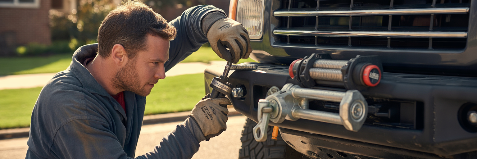
With your tools staged and hardware verified, you are ready to begin the physical off-road winch installation. Working methodically through the mechanical mounting phase prevents pinched fingers, stripped frame threads, and the dreaded scenario of unbolting a 90 pound assembly just to attach a forgotten fairlead bracket.
Prepping the Frame Horns and Sequencing the Fairlead First
Start by parking your vehicle on level concrete, engaging the parking brake firmly, and placing heavy rubber wheel chocks behind both rear tires. Pop the hood and use a 10mm or 12mm wrench to disconnect the negative battery terminal first, wrapping the loose lead in a shop towel so it cannot spring back against the post. Disconnecting the ground cable eliminates the risk of shorting tools later and guarantees you will not accidentally disturb front crash zone airbag sensors while unbolting bumper structures.
Remove the front grille, plastic valence panels, and lower factory skid plates to expose the bare steel frame horns. With the lower splash guards out of the way, take two minutes to inspect your exposed sway bar links, tie rod ends, and steering rack bushings for torn boots or play; if you have noticed front end pops recently, check our diagnostic guide on why a car makes a clunking noise when turning the steering wheel while everything is wide open. Next, wire brush any surface rust or caked trail mud off the frame mounting pads. Run a matching tap or thread chaser lubricated with cutting oil through all factory frame weld nuts to clear out corrosion and rock grit, then mist any bare steel scratches with rust preventative chassis paint.
Before lifting the winch, follow two critical sequencing tricks that save hours of frustration. First, flip the winch onto its back on a cardboard sheet and slide the four square capture nuts into the recessed pockets inside the mounting feet. Place a small piece of painter tape over each slot or pack a dab of thick wheel bearing grease behind the nuts so they cannot slide out onto the driveway when you tilt the winch into the bumper. Second, bolt your aluminum hawse or steel roller fairlead onto the front of the bumper or cradle plate right now. Once the winch body sits four inches behind the bumper face, there is zero clearance to fit a wrench or fingers onto the back of the lower fairlead bolts.
Clocking the Gearbox Housing for Clutch Lever Access
Before bolting the winch down, test fit the unit or measure how the free spool clutch handle aligns with your bumper top plate. On many recessed hidden cradles and low profile steel bumpers, the factory position of the clutch lever hits the backside of the grille or points straight down toward the skid plate where you cannot reach it. Fortunately, most planetary winches allow you to rotate, or clock, the gearbox housing relative to the mounting feet.
To clock the gearbox, set the winch on your workbench and use an Allen hex key or Torx bit to remove the eight or ten small perimeter cap screws that secure the aluminum gearbox end housing to the drum support tie rod bracket. Do not pull the housing completely off the shaft, or the internal planetary gear assemblies may slide out of mesh. Instead, gently tap the gearbox housing with a rubber mallet and rotate it in 36 degree or 45 degree increments until the clutch handle points straight up into your bumper access cutout. Take care not to tear the thin paper sealing gasket seated between the castings. If your winch housing features a small threaded water drain plug, ensure it remains oriented near the bottom gravity point, then reinstall the perimeter cap screws with a tiny dab of blue threadlocker and tighten them evenly in a crisscross pattern.
Torquing the Winch Body and Threading the Recovery Lead
Lifting an 85 pound steel cable winch into a chest high truck bumper by hand is a recipe for lower back strain or crushed knuckles. If you are working solo, rest the winch on the saddle of a hydraulic floor jack padded with a scrap piece of two by four lumber, roll it under the front end, and pump the unit smoothly up into the cradle cavity, or recruit a helper to steady the load while you start the bolts.
Apply two drops of medium strength blue threadlocker to the threads of your four 3/8 inch Grade 8 or M10 Class 10.9 mounting bolts, slide a lock washer and flat washer onto each, and thread them up through the 6mm cradle plate into the square capture nuts by hand. Never tighten one bolt completely before starting the others, as you need slight play to align all four corners. Once all four fasteners thread smoothly without cross threading, snug them down and use your calibrated torque wrench in an X pattern to tighten them to the manufacturer specification, which typically falls between 30 and 45 foot pounds.
With the winch anchored, rotate the clutch handle to the disengaged free spool position. Pull the taped end of your synthetic rope or steel cable off the bottom of the drum and thread it straight out through the pre mounted fairlead throat before cutting away the factory shipping tape keeping the drum coils tight. Attach your forged steel clevis hook or closed system recovery thimble to the eyelet, slide the heavy clevis pin through, and bend the legs of the stainless steel cotter pin firmly around the shaft so it cannot vibrate loose on washboard roads. Give the clutch handle a full sweep back and forth to verify it clears the bumper sheet metal cleanly and check that the cradle brackets sit flush against the frame horns without gaps.
Routing High-Amperage Wiring and Solenoid Control Boxes
Mechanical strength means nothing if poor electrical routing starves your motor of current or causes a dead short on the trail. Properly wiring a truck winch requires managing extreme direct current amperage loads while shielding heavy copper cables from engine heat, sharp frame stampings, and deep water crossings.
Integrated Versus Remote-Mounted Solenoid Control Boxes
Winch designs split into two configurations for housing the heavy duty contactor solenoid pack that switches power to the motor windings: integrated bridge mounts and remote modular boxes. Integrated winches mount the control pack directly across the top tie rods above the spool drum. While an integrated unit arrives pre wired from the factory and simplifies installation into just running two main battery leads, the tall bridge housing blocks significant radiator airflow when mounted outside the grille and places sensitive electronics low in the splash zone.
Modular winches let you unbolt the solenoid box from the tie rods and relocate it under the hood on an inner fender apron or firewall bracket using extended motor leads. When wiring a truck winch for deep water fording or muddy forestry roads, remote mounting the solenoid box high in the engine bay keeps the internal copper contactors and wireless remote receiver module high and dry while dropping the physical height of the winch by three inches to clear tight hidden bumper cavities.
Preventing Voltage Drop and Routing Heavy-Gauge Cables Safely
Understanding 12 volt direct current physics is vital here. Because automotive electrical systems operate at low voltage, delivering the horsepower needed to pull a mired four wheel drive truck requires massive amperage, often exceeding 400 amps under heavy strain. Any extra resistance in the circuit triggers severe voltage drop across the cable run. When voltage drops at the motor terminals, amperage spikes even higher and turns your wiring into a glowing heating element, starving the motor of torque and melting plastic insulation.
Always use the supplied heavy gauge, fine strand copper cables (typically 2 AWG or 1/0 AWG). Never cut and splice winch cables with crimp butt connectors to lengthen them, and never coil up excess cable length like a garden hose, which creates an inductive heat coil under load. As highlighted in the recovery wiring guidelines from Offroad.net, if you are mounting a winch on a rear bumper or routing to a bed mounted dual battery setup, you must step up the entire continuous wire gauge from end to end using hydraulically crimped copper lugs to prevent resistance heat buildup and install a high amp fuse or breaker right at the battery.
Begin routing at the winch motor terminals rather than the battery. Connect the color coded three phase motor leads (standardly yellow, blue, and red) from the solenoid box to the corresponding studs stamped A, F1, and F2 on the motor casing. Hold the lower hex nut stationary with an open end wrench while tightening the top nut so you do not twist the internal copper terminal bolt inside the motor housing and snap the brush connections. Wrap the long positive and negative battery cables inside corrugated split loom tubing and route them up through the radiator core support using rubber grommets around any sheet metal holes. Keep the harness at least six inches away from hot exhaust manifolds, steering intermediate shafts, and suspension control arms. Navigating crowded full size V8 engine bays requires careful planning around dual alternators and fuse blocks, a layout familiarity that also helps when following our guide on how to diagnose common issues in the Chevrolet Silverado. Anchor the loomed cables to factory frame brackets or main wiring harnesses every 12 inches using heavy duty UV resistant zip ties.
Battery Terminal Connections, Grounding, and Corrosion Sealing
Mount your manual rotary cutoff switch or high amp thermal circuit breaker on a solid bracket within 6 to 12 inches of the positive battery terminal, connecting it with a short 2 AWG copper jumper cable. Placing the switch right at the battery post ensures that when you turn the knob off for highway driving, the entire five foot cable snaking down through your front grille and bumper is completely dead and safe from collision shorts.
When connecting the heavy black ground cable, bolt it directly to the negative post of your primary starting battery (or the dedicated accessory stud on top post AGM batteries). Never ground a 400 amp winch to a painted frame bolt or thin inner fender sheet metal. Steel chassis rails have far higher electrical resistance than stranded copper cable, and attempting to pull 400 amps through the frame will overload and melt your small factory battery to body ground strap. Before bolting any lugs down, remember to slide the protective red and black rubber terminal boots onto the cables. Tighten the terminal nuts firmly, coat every exposed copper stud on the battery, cutoff switch, and winch motor with dielectric grease or anti corrosion terminal spray to block galvanic oxidation, slip the rubber boots over the studs, and reconnect your main vehicle negative battery lead. Before starting the truck, have a helper turn the steering wheel from full left lock to full right lock while you watch under the fender liner to verify the tires and pitman arm never rub the power cables.
Pre-Trail Testing and Spooling the Line Under Load
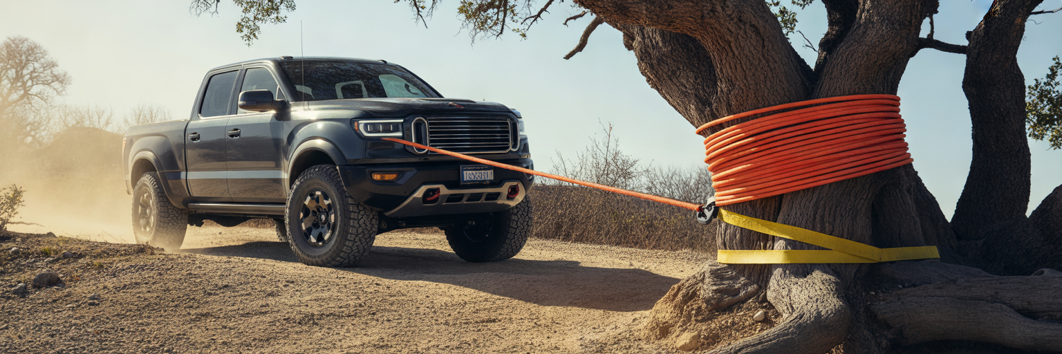
Your mechanical fasteners are torqued and your electrical circuit is live, but your rig is not ready to tackle a muddy trail recovery yet. Commissioning a newly installed winch requires verifying directional phasing and properly stretching the recovery line under controlled load.
Initial Driveway Function Checks and Remote Verification
Start the vehicle engine and let it idle in Park or Neutral with the parking brake locked. Turn your under hood rotary cutoff switch to the On position and plug the corded handheld remote into the solenoid box socket (or power on your wireless handset). Stand clear of the fairlead and tap the Out trigger for two seconds. Verify that the drum rotates in the correct direction to pay line out from the bottom of the spool, just above the mounting plate. Unless you own a specialized industrial unit, standard off-road winches are engineered to pull from the bottom of the drum so the load force pulls aligned with the mounting bolts rather than leveraging across the top of the housing.
Next, tap the In trigger for two seconds to confirm the drum reverses cleanly and winds the line back in. Unplug the remote and rotate the mechanical clutch lever from Engaged to Free Spool. Pull two feet of line out by hand to verify the drum spins smoothly without metallic scraping, then turn the lever back to Engaged and confirm the internal sliding ring gear locks cleanly into the planetary carrier.
Stretching and Pre-Tensioning the Winch Line Under Load
A brand new winch straight out of the cardboard shipping box has zero tension on its drum wraps. At the factory, assembly workers wind the synthetic rope or steel wire loosely onto the spool solely for packaging convenience. If you hook up to a stuck truck on the trail with a loose factory wind, the top layer of rope under 8,000 pounds of tension will knife straight down into the soft, spongy lower wraps. On a synthetic line, this burial pinches and abrades the polymer fibers against themselves; on a steel cable, it crushes and kinks the wire while wedging the line so tightly that the drum locks solid. Conditioning your line before its first real emergency is just as critical for mechanical longevity as following our guide on how to bed in brake pads after a DIY installation. Follow this six step procedure to stretch and pre tension your line properly:
- Find a long, flat or gently sloped driveway or quiet graded dirt road with a solid stationary anchor point at the end, such as the base of a mature tree or a second heavy parked truck.
- Disengage the winch clutch lever into Free Spool and walk the hook out manually until exactly 5 full wraps remain around the bare drum barrel for synthetic rope, or 8 full wraps remain for steel cable; never unspool past this painted warning mark, because the tiny M6 button head screw holding the rope tab to the drum is only meant to start the wind and will rip out instantly without the friction grip of those base wraps.
- Wrap a wide polyester tree saver strap low around your anchor point, attach your winch hook or thimble via a rated shackle, and flip the winch clutch lever back into the Engaged position.
- Have a trusted helper sit in the driver seat of your winching vehicle with the engine idling to keep the alternator charging, shift the transmission into Neutral, release the parking brake, and press the service brake pedal lightly to create roughly 500 to 1,000 pounds of steady rolling drag as the vehicle rolls toward the anchor.
- Stand at least eight feet to the side of the tensioned line using your remote controller and pulse the winch In slowly, steering or guiding the vehicle so the line stacks onto the drum in tight, neat, consecutive coils from one flange to the other while keeping your gloved hands at least four feet away from the fairlead by holding the fabric hook safety strap.
- Once the line is wound within three feet of the fairlead, stop winching, have the driver set the parking brake and shift into Park, disconnect from the anchor, and use your calibrated torque wrench to re check all four winch foot bolts and frame cradle bolts to account for initial metal seating under load.
Taking twenty minutes to pack those lower wraps tightly onto the drum barrel ensures your line will never knife into itself when you are buried to the differentials in a remote canyon.
Essential Off-Road Winching Safety Protocols and Post-Use Maintenance
A 12,000 pound winch is an industrial piece of rigging machinery mounted to the nose of your daily driver. Respecting the forces involved and maintaining the mechanical components after muddy trail runs guarantees your setup works safely five years down the road.
Line Dampers, Safe Bystander Zones, and Proper Anchor Rigging
Every hands-on technical craft relies on non negotiable safety rules and protective equipment to prevent severe injury, much like understanding why single-use needles are essential for safe tattoos illustrates how strict equipment standards protect practitioners in specialized environments. On the trail, your first rule is putting on heavy cowhide leather gloves before touching any rigging gear. Steel cables inevitably develop broken wire strands known as fishhooks that slice bare palms to the bone, while synthetic ropes pick up sharp rock splinters and silica grit that cause severe friction burns if the line slips through bare fingers.
Before applying tension to any recovery pull, drape a weighted vinyl winch line damper, a heavy canvas tool bag, or even a thick winter jacket over the middle third of the extended line. If a shackle pin shears or a worn cable parts under load, that concentrated downward mass absorbs the upward whip energy and forces the broken line straight into the dirt within a few feet rather than allowing it to recoil toward the vehicle cab. Enforce a strict bystander exclusion zone before touching the remote switch: clear all passengers, pets, and spotters out of the snap back radius, keeping everyone at least 1.5 times the total extended length of the winch line away from the axis of the pull. If you are operating the winch solo from inside the cab, pop the hood latch and prop the hood fully open to create a steel blast shield in front of your windshield.
Rig your anchor points with equal discipline. Never wrap your winch cable or synthetic rope directly around a tree trunk or boulder and hook the clevis back onto the main line. Doing so girdles the cambium bark layer and kills living trailside trees while kinking steel wire rope and slicing synthetic fibers cleanly in half. Always wrap a wide three inch non stretch polyester tree saver strap around the base of the trunk, bring the two sewn eyes together, and link your winch hook or closed thimble to the strap using either a rated forged steel bow shackle (always threading the shackle pin all the way in until seated and then backing it off one quarter turn so tension does not seize the threads) or a high strength synthetic soft shackle.
Managing Alternator Duty Cycles and Long-Term Winch Upkeep
During a long uphill pull, your vehicle charging system is working at a steep deficit. While your winch motor is drawing 350 to 400 amps under load, a typical factory truck alternator only produces 130 to 180 amps at highway cruising RPM and often less than 80 amps at curb idle. The battery reserve bridges that gap, which means continuous winching will rapidly drain your battery and overheat both the alternator diodes and the winch motor armature.
Always keep the engine running during any recovery pull, and use a slight throttle bump or idle up switch to hold engine speed around 1,500 RPM so the alternator cooling fan spins rapidly and outputs stronger current. Watch your dashboard voltmeter closely; if system voltage drops below 11.5 volts, stop pulling immediately and let the engine idle for five minutes to replenish the battery. Respect your winch motor thermal duty cycle by pulling in steady 30 to 60 second intervals, then pausing for several minutes to touch the motor housing with the back of a gloved hand; if the cylinder is too hot to hold your hand against, let it cool so the internal copper winding varnish does not melt.
Once you return home from the trail, perform these routine maintenance steps to keep your recovery system reliable:
- Unspool your synthetic rope completely on the driveway after muddy or sandy runs and rinse the braided fibers gently with a low pressure garden hose so trapped microscopic silica grains do not act like internal sandpaper and saw through the core strands during your next pull.
- Inspect steel wire cables foot by foot as you wind them back in under light tension, retiring the line immediately if you spot flattened sections, birdcaged wire strands, sharp kinks, or clusters of broken wires.
- Wipe road salt and mud off the motor casing and battery cutoff switch, checking that all rubber terminal boots remain supple and free of splits.
- Exercise the winch once a month during the off season by unspooling 20 feet of line and powering it back in, which warms the motor to evaporate internal condensation and distributes lithium grease across the upper planetary gear teeth and bearing seals.
Pairing a properly installed, load tested winch with a dedicated recovery kit containing a tree saver strap, two rated shackles, a snatch block pulley, and a line damper gives you the self reliance to explore remote trails with total confidence.