
Since the early 2000s, automakers have steadily phased out mechanical hand-lever cables in favor of computer-controlled electric rear actuators to free up cabin space and integrate driver assistance features. However, what makes hill-starts effortless on the road turns a routine Saturday afternoon rear brake job into an expensive mechanical trap if you treat the caliper like a traditional hydraulic setup. Performing a successful electronic parking brake pad service requires understanding how software and hardware work together inside the rear wheel well before you ever loosen a caliper bolt.
Understanding Electronic Parking Brake Pad Systems and Designs
For decades, securing a parked vehicle relied entirely on muscle power pulling a braided steel cable stretched beneath the chassis. Today, that ratcheting lever or heavy foot pedal has been replaced by a compact dashboard switch wired to an electronic control unit. Instead of dealing with stretched cables and rusted equalizer bars, modern vehicles command dedicated electric motors to apply precise clamping pressure at the rear axle.
Caliper-Integrated Actuators vs Cable-Puller Modules
Before raising the rear end of your car, you need to know which of the two primary electronic architectures your manufacturer installed. The first and less intrusive design is the electronic cable-puller system. Found on many heavy-duty pickups and larger SUVs, this setup uses a central electromechanical module mounted under the frame to pull traditional steel cables. Those cables connect to standard mechanical calipers or small drum-in-hat parking brake shoes tucked inside the rear rotor bell. If your truck uses a drum-in-hat cable puller, swapping the main exterior disc pads works just like a conventional hydraulic brake job.
The second and far more common design on modern passenger cars, crossovers, and light trucks is the motor-on-caliper system. Here, a black composite motor housing bolts directly onto the back of the cast-iron or aluminum rear brake caliper. An electrical wiring harness plugs straight into the caliper body alongside the rubber hydraulic brake hose.
Internal Anatomy of a Motor-on-Caliper Unit
Inside a caliper-integrated unit, hydraulic fluid pressure and electromechanical gearing live in the exact same bore. A small direct-current electric motor sits inside the outer housing, spinning at high speed when you pull the cabin switch. Because a tiny motor cannot generate enough raw torque to hold a two-ton vehicle on a steep driveway by itself, it feeds into a multi-stage reduction assembly.
As detailed in the technical engineering breakdown by HELLA Tech World, this drive unit typically uses a toothed belt or gear wheel paired with a compact planetary gearset to multiply torque immensely before turning a threaded spindle located inside the hollow hydraulic piston. Depending on the brake supplier, this spindle moves a threaded drive nut, a worm gear, or a ball-in-ramp mechanism straight forward until it presses solidly against the inside face of the piston head. Once the mechanical nut locks the piston against the brake pad, the electric power cuts off and the friction of the screw threads holds the car stationary without draining the battery.
Shared Friction Surfaces and Automated Wear Patterns
Because the internal spindle pushes the exact same piston used by the master cylinder, both normal foot braking and parked clamping share the same electronic parking brake pad and rotor friction surfaces. There are no separate parking shoes in a motor-on-caliper setup.
This shared workload explains why many drivers are surprised to find their rear pads worn down to the metal wear indicators at thirty thousand miles while the front pads still have half their life left. Modern vehicles constantly pulse the rear calipers without your foot ever touching the brake pedal. Automated brake hold at red lights, hill-start assist, adaptive cruise control speed adjustments, and electronic stability control interventions rely heavily on rear caliper modulation to keep the cabin level and prevented from pitching forward. As we cover in our guide on how front and rear brake pads differ for new owners, these automated background tasks completely invert traditional front-to-rear wear ratios. Taking thirty seconds to peer through your rear wheel spokes to confirm whether a black motor housing and wire harness are bolted to your caliper is the foundational first step before picking up a wrench.
Why Maintenance Mode Is Essential Before Piston Retraction
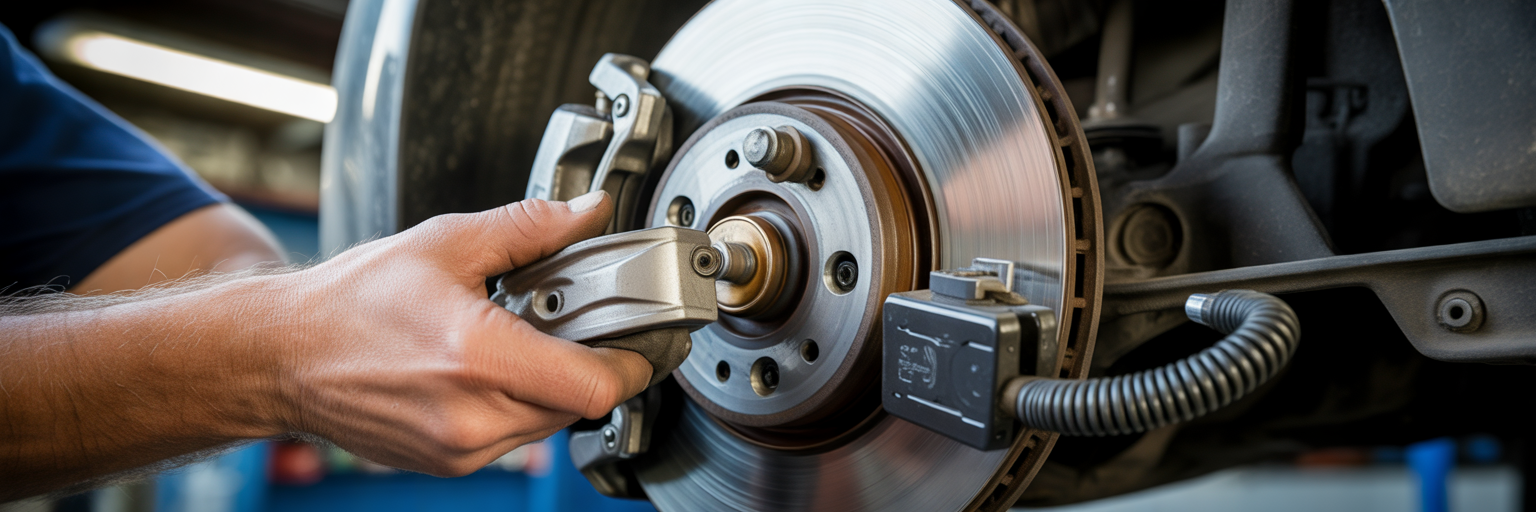
Once you confirm that your vehicle uses caliper-integrated electric motors, your approach to pushing the caliper piston back into its bore must change completely. On a standard front caliper, the inside of the piston is an open hollow cup filled only with liquid brake fluid. Pushing that piston back simply forces fluid up the lines into the master cylinder reservoir.
The Mechanical Lockup Behind the Hydraulic Piston
Inside an electronic rear caliper, the hollow piston cavity is occupied by the high-strength steel spindle and its threaded drive nut. Even when you release the parking brake switch inside the cabin to drive away, the electric motor only backs that internal nut off by a fraction of a millimeter. It stays parked right behind the piston head intentionally.
Brake engineers program the nut to hover just behind the piston face to automatically compensate for friction material wear and ensure the parking brake clamps in less than a second when parked. As your brake pads get thinner over thousands of miles, the internal threaded nut creeps steadily outward to follow the piston. When you remove worn pads to install thick new ones, that solid steel nut acts as an immovable mechanical wall directly behind the piston.
Financial Cost of Forcing an Unretracted Caliper
If a home mechanic attempts to retract rear caliper piston assemblies using a heavy C-clamp or a traditional hand-turned wind-back cube tool without first commanding the internal nut to spin backward, metal-on-metal destruction happens immediately. Forcing the piston against the stationary spindle transfers hundreds of pounds of leverage straight into the delicate planetary reduction gears.
You will often hear a sickening plastic snap as the internal composite gear teeth shear off, the threaded spindle bends out of alignment, or the outer motor housing cracks open. What started as an affordable forty-dollar DIY rear brake replacement instantly turns into a repair bill ranging from four hundred to nearly a thousand dollars per wheel. You are left buying a new caliper and actuator motor assembly, bleeding the hydraulic circuit, and potentially paying shop rates for module initialization, which quickly approaches the dealership brake service pricing we broke down for modern vehicles.
Risks of Backyard Bypass Hacks and Manual Motor Removal
When faced with an unretracted caliper in the driveway, many DIYers look for shortcuts to bypass the car’s computer. One common backyard method involves unplugging the caliper harness and touching twelve-volt jumper leads from a drill battery or car battery directly to the two bare motor pins. While reversing polarity does spin the motor backward, there is no electronic current sensing to stop it when the internal nut reaches the back of the housing. Leaving the jumper wires connected for even half a second too long jams the threaded nut hard against the internal stop collar, locking the motor permanently.
Another manual workaround involves removing the two small Allen or Torx bolts holding the black plastic motor onto the metal caliper body, pulling the motor off, and turning the exposed internal Torx shaft clockwise by hand. While manual unbolting works as an emergency fallback if a scan tool fails, it carries real physical headaches in regions that salt winter roads. The tiny fastening bolts frequently corrode into the aluminum caliper housing and snap off during removal. Furthermore, disturbing the fragile rubber O-ring between the motor and caliper body often pinches the seal, letting water and road grime enter the gearset and triggering dashboard fault lights a few months after your brake pad replacement is finished.
| Retraction Method | Internal Spindle Effect | Hydraulic Piston Effect | Component Failure Risk |
|---|---|---|---|
| Electronic Service Mode Command | Motor winds threaded nut fully to home position | Remains extended until pressed with flat spreader | Minimal when battery voltage remains above 12 volts |
| Manual Motor Unbolting and Torx Wind-Back | Hand tool turns internal screw without motor power | Allows straight compression once screw is seated | Moderate risk of torn O-ring seals and corroded housing bolts |
| Direct 12V Battery Jumper Leads | Spins motor unregulated until physical hard stop | Remains extended until pressed manually | High risk of reverse polarity spike or over-retraction jam |
| Forcing with C-Clamp Without Retraction | Crushes stationary spindle and strips reduction gears | Binds in bore or cracks piston rear face | Severe risk requiring complete caliper and actuator replacement |
This comparison outlines the mechanical outcomes of different retraction methods based on standard motor-on-caliper engineering designs used across domestic, European, and Asian vehicle platforms. Always remember that commanding the internal screw mechanism backward electronically is a separate prerequisite that clears the path before you ever apply physical pressure to compress the hydraulic piston.
Tools and Preparation for a Safe Rear Brake Job
Staging your garage bay properly prevents mid-job surprises when working with computer-monitored braking systems. Because you will be working with the vehicle’s ignition powered on and the rear braking mechanism completely disabled, both electrical stability and physical anchoring require careful attention before you touch the lug nuts.
Diagnostic Equipment and Voltage Stabilization
One of the most overlooked hazards during an electronic brake job is a weak twelve-volt car battery. Winding both rear actuator motors all the way back and holding the chassis control modules awake with the ignition turned on draws substantial amperage. If your battery voltage sags below the manufacturer’s programmed threshold while the calipers are transitioning, the ABS or parking brake module can abort the sequence mid-travel and lock up in an error state.
Connecting a smart battery charger or voltage maintainer to the under-hood battery terminals before starting keeps system power steady above twelve point five volts. Alongside stable power, having the right diagnostic tool or confirmed cabin procedure ready ensures you aren’t searching forums with your car already up on stands.
Mechanical Tools and Vehicle Stabilization
On the mechanical side, you must put away the old rotating cube tool used on older mechanical rear calipers. Modern electronic pistons do not rotate to retract; the internal nut spins while the outer piston slides straight in and out. Twisting an electronic caliper piston with a pronged wind-back tool can tear the rubber dust boot, scratch the protective phenolic or anodized piston coating, or snap the internal anti-rotation guides inside the bore. You only need a flat-faced straight-push pad spreader. If you are building out your garage kit from scratch, review our complete tool checklist for first-time DIYers to make sure your sockets, torque wrenches, and safety gear are accounted for.
Physical vehicle stabilization is equally critical.The moment you command the rear calipers into maintenance mode, the parking brake releases entirely and the rear hubs will spin freely. Never rely on a hydraulic floor jack or the transmission park pawl alone to hold the vehicle while you pull on heavy suspension fasteners.
- Heavy-duty rubber wheel chocks wedged tightly in front of and behind both front tires on level concrete.
- A twelve-volt battery maintainer or smart charger clipped to the vehicle battery terminals to prevent low-voltage module faults.
- A bidirectional OBD-II scan tool or wireless smartphone diagnostic dongle capable of commanding chassis and EPB service functions, if required by your make.
- Properly rated steel jack stands positioned under the manufacturer-specified rear pinch welds or reinforced frame rails.
- A flat-plate, straight-push brake caliper press or parallel pad spreader tool to push the hydraulic piston straight back without twisting it.
- High-temperature pure silicone brake grease and a wire brush for cleaning bracket lands and lubricating slide pins.
- A sturdy steel mechanics wire hanger or bungee hook to suspend the heavy motor-on-caliper assembly from the suspension spring without straining the wiring harness.
Methods to Activate Brake Service Mode Across Vehicle Types
With the front wheels chocked and your battery supported, the next step is commanding the vehicle computer to wind the internal actuator spindles all the way back to their home position. Automakers refer to this software state as brake service mode, maintenance mode, or pad replacement position. Depending on what sits in your driveway, you will trigger this state through one of three interfaces.
Bidirectional OBD-II Scan Tool Procedure
European manufacturers including Volkswagen, Audi, BMW, Volvo, and Mercedes-Benz, along with several late-model domestic trucks, require a bidirectional OBD-II scan tool to open the rear calipers. Unlike a basic twenty-dollar code reader that only reads check engine lights, a bidirectional scanner can send active movement commands back to the vehicle modules.
To use a scanner, plug the connector into the OBD-II port under the steering column and turn the ignition to the Key On, Engine Off position. Release the parking brake switch so the calipers are not clamped. Navigate through the scanner menu to Special Functions, Service Reset, or Chassis Electronic Parking Brake. As highlighted in an industry diagnostic overview by Vehicle Service Pros, you should always check for and clear any stored ABS or parking brake fault codes before initiating the retraction command, as active faults will block the module from responding. Select the option to open or retract the calipers for pad replacement and wait for the tool screen to confirm completion.
Dashboard Switch and Pedal Combination Sequences
Many high-volume Asian and domestic brands, including Ford, Mazda, Honda, Toyota, Subaru, and Nissan, engineered built-in dashboard button sequences so technicians and owners can trigger maintenance mode without plugging in a scanner. While the exact button dance varies by brand, the logic usually involves holding the accelerator pedal to the floor while pressing the parking brake toggle switch downward into the release position while cycling the ignition power button.
Timing matters during these manual sequences. Most modules require you to complete the ignition cycle and switch hold within five to eight seconds, and you must keep your foot completely off the hydraulic brake pedal unless the factory manual specifically calls for it.
Infotainment Screen Service Menus
On newer software-defined vehicles, electric pickups, and modern luxury sedans such as Tesla, Rivian, and recent Mercedes-Benz models, the retraction command lives directly inside the central infotainment touchscreen or digital gauge cluster submenu. Owners simply place the vehicle in Park, open the Vehicle Settings or Service screen, select Brake Pad Replacement Mode or Tow/Maintenance settings, and confirm the prompt on the display.
| Vehicle Group Examples | Primary Retraction Trigger | Cabin Prerequisite State | Cluster Confirmation Signal |
|---|---|---|---|
| Ford, Mazda, and Nissan | Dashboard switch held down with accelerator depressed | Ignition in On position with engine off and foot off brake pedal | Yellow parking brake icon illuminates steady or maintenance message displays |
| Volkswagen, Audi, and BMW | Bidirectional OBD-II scan tool command | Battery maintainer connected and parking brake switch released | Audible three second motor wind-back and flashing cluster indicator |
| Toyota, Lexus, and Subaru | Rapid triple press and hold of parking brake switch | Ignition on with foot brake held during initial unlock phase | Parking brake indicator flashes slowly after motor stops whirring |
| Tesla, Rivian, and Late-Model Mercedes | Infotainment touchscreen service menu or steering wheel cluster submenu | Vehicle in Park with driver door closed and PIN or pedal verification | Screen displays brake pad replacement position active confirmation |
Activation requirements vary by model year and trim level, so home mechanics should always cross-reference their factory service documentation prior to performing button sequences.
Sensory Confirmation and Troubleshooting Activation Refusals
Never assume the vehicle entered maintenance mode just because a light blinked on the dash. Use your ears to confirm the mechanical retraction. When the command succeeds, you will hear a distinct, continuous high-pitched electric whirring sound from both rear wheel wells lasting roughly two to four seconds as the internal spindles spin all the way back. Once the motors go silent, the instrument cluster will display a flashing yellow parking brake wrench icon or a text banner stating that brake maintenance mode is active.
If your car refuses to wind the motors back, check these five common culprits before assuming a part is broken:
- An open driver door or unlatched trunk lid, which many safety modules treat as an unsafe condition that blocks electronic caliper movement.
- Resting your foot on the hydraulic brake pedal during a button sequence that requires zero fluid pressure in the lines.
- Battery voltage sitting below 11.8 volts with the ignition on, causing the control module to reject high-draw motor commands.
- An active ABS wheel speed sensor code or preexisting chassis fault stored in computer memory that locks out maintenance routines.
- Pulling the parking brake switch upward toward the apply position rather than pushing it firmly downward into the release position during the sequence.
Once you hear the three-second motor wind-back complete and see the maintenance light stay illuminated on the cluster, switch the ignition completely off before walking back to the rear wheels.
Step-by-Step Rear Pad Removal and Piston Compression
With the internal actuator spindle safely parked at the back of the housing and the ignition turned off, you can lift the rear of the vehicle, support it on jack stands, and remove the rear wheels. From here, the physical wrenching closely resembles a standard floating caliper job, with a few vital precautions to protect the electrical hardware.
Protecting the Actuator Wiring Harness and Unbolting the Caliper
Before putting a socket on the caliper guide pin bolts, inspect the plastic electrical connector plugged into the back of the actuator motor. Because the rear calipers sit directly in the path of water, slush, and gravel kicked up by the tires, these plugs get caked in grit. Brush away loose dirt around the connector lock tab.
On some vehicles, the electrical harness has plenty of slack to leave it plugged in while you lift the caliper off the bracket. However, if the wire loom looks short or taut, release the secondary safety lock tab and unplug the harness before unbolting the caliper. Never let the weight of the caliper hang by its electrical wires; stretching the thin copper strands inside the insulation causes intermittent open-circuit faults that will trigger warning lights weeks later. Unbolt the two rear slide pin bolts, lift the caliper off the rotor, and immediately hang it from the suspension coil spring using your mechanics wire hook.
Straight Piston Compression and Fluid Reservoir Monitoring
Before compressing the piston, walk to the front of the car and pop the hood to unscrew the brake fluid reservoir cap. Wrap a clean shop rag around the neck of the reservoir. If someone previously topped off the brake fluid while the old pads were worn thin, pushing the rear pistons back can cause corrosive DOT 3 or DOT 4 fluid to overflow onto painted frame rails. If the fluid is already near the maximum line, use a clean turkey baster or fluid syringe to draw out an ounce or two first.
Back at the rear wheel, place an old brake pad flat against the face of the caliper piston and position your straight-push pad spreader tool inside the caliper cavity. Turn the spreader handle slowly and steadily. Because the internal screw is already retracted out of the way, the hydraulic piston should slide straight back into its bore smoothly with moderate hand pressure. If the piston hits a rock-hard wall halfway in, stop immediately; do not put a cheater pipe on the tool. A hard stop means the electronic spindle did not fully retract, and you need to re-verify service mode before applying more force.
Bracket Preparation and Piston Notch Alignment
While the caliper is suspended safely to the side, pull the old pads out of the mounting bracket and inspect your brake discs. Rear rotors on electronic parking brake vehicles frequently develop rust ridges along the outer edge or scoring from automated brake applications, so check our guide on how to know when rotors need replacing with brake pads to verify whether you need fresh discs before reassembly.
Pop the old stainless steel abutment clips off the caliper bracket and scrub the metal seating lands with a wire brush until the cast iron is free of rust scale. Packed rust underneath the new clips will bow the metal upward and pinch the ears of your new brake pads, causing them to drag and overheat the electronic caliper. Pull the slide pins out of their rubber boots, wipe away old gummy grease, and coat them lightly with pure silicone brake paste before pressing them back in.
Before sliding the caliper back over the new pads, look closely at the face of the hydraulic piston and the metal backing plate of your new inner brake pad. Even on electronic systems that compress straight in, certain caliper pistons feature two machined notches or cross grooves across their face. If your new inner brake pad has a raised metal nib or locator bump on the backplate, that pin must drop cleanly into the notch on the piston face. If the piston face sits cocked on top of the metal nib, the caliper will wedge at an angle, causing severe tapered pad wear and stalling the electronic actuator during calibration. Seat the caliper squarely over the new pads, torque the slide pin bolts to factory specification, and click the electrical connector firmly back onto the motor terminal until the locking tab snaps shut.
Exiting Service Mode and Post-Installation Safety Checks
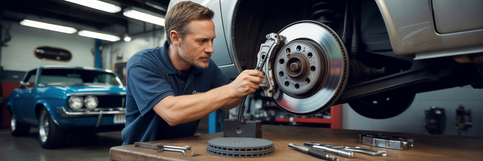
Once both rear wheels are bolted back on and torqued to spec on the ground, resist the urge to immediately grab the parking brake switch or command the scan tool to close the calipers. Jumping straight to electronic initialization with a wide hydraulic air gap is the number one reason DIYers trigger a flashing fault light at the very end of the job.
Seating Hydraulic Pistons Before Electronic Initialization
Right now, both hydraulic pistons are pushed all the way back at the bottom of their bores, leaving several millimeters of empty space between the piston face and the new pad backing plates. If you command the electronic actuator motors to exit service mode while that gap still exists, the electric spindle will spin forward far longer than normal trying to find resistance. Many chassis modules monitor spindle rotation counts; if the motor spins past its expected travel window without feeling clamping tension, the computer assumes a mechanical failure occurred and locks the system down with an out-of-range fault code.
Sit in the driver seat and pump the foot brake pedal firmly five to ten times before touching any electronics. The first two strokes will sink nearly to the floor as master cylinder fluid fills the caliper bores. Keep pumping until the pedal feels rock solid and high. Pumping the foot pedal moves the hydraulic pistons flush against the new brake pads, eliminating the air gap so the electric spindle only has to travel its normal calibrated distance.
Commanding EPB Actuator Calibration and Stroke Verification
With a firm foot pedal established, you are ready to perform the electronic parking brake reset and exit maintenance mode. If you used an OBD-II scan tool, reconnect it with the ignition on and select the function to close calipers or exit pad replacement mode. If you used a dashboard switch sequence, repeat the exact entry procedure, holding the parking brake toggle switch upward in the apply direction instead of pushing it down.
Listen closely during this initialization phase. The vehicle automatically runs an EPB actuator calibration routine to learn the exact thickness of your newly installed pads. You will hear the rear motors wind forward for several seconds, clamp down firmly against the rotors until current draw spikes, release slightly to set the running air gap, and sometimes clamp a second time to verify stroke sensor positioning. Once the motors stop, the flashing yellow maintenance icon on the instrument cluster will extinguish.
- Pump the hydraulic foot brake pedal five to ten times with the engine off until the pedal feels firm and high at the top of its travel.
- Execute the service mode exit command via your scan tool, infotainment menu, or upward dashboard switch sequence with the ignition on.
- Cycle the parking brake switch from fully applied to fully released three complete times, listening to ensure both left and right motors start and stop in unison.
- Test physical holding power on a gentle driveway incline in Neutral, then release the switch to verify the vehicle rolls freely with zero pad drag.
- Perform a final diagnostic scan of the ABS and parking brake modules to clear any low-voltage or communication fault codes logged during service.
Clearing Diagnostic Faults and Bedding In New Friction Material
If a yellow or red brake warning light remains flashing after you exit maintenance mode, do not panic. First, plug in your scan tool and read the fault code. Frequently, unplugging the caliper harness while the car was awake logs a temporary open-circuit history code that simply needs to be cleared via the scanner. If the code refuses to clear and states an open circuit on the left or right actuator, crawl back under the rear bumper and push firmly on the plastic harness plug; nine times out of ten, the weatherproof rubber seal inside the plug prevented the locking tab from clicking all the way home.
Finally, take the vehicle out on a quiet stretch of road to mate the new friction pads to the rotor surfaces. Following a structured heat-cycling routine transfers a microscopic layer of pad material evenly onto the cast iron, preventing brake judder and maximizing stopping bite. You can follow the exact speed and cooling intervals in our step-by-step guide on bedding in new brake pads to finish the process safely. Never pull the electronic parking brake switch while moving to bed in the pads, since the normal hydraulic pedal already uses the exact same friction surfaces. Once your pedal feels crisp, the actuators clamp quietly on command, and your dashboard is free of warning lights, your rear brakes are ready for thousands of miles of dependable driving.