Since disc brakes replaced four-wheel drum setups on mainstream American passenger cars in the 1970s, the cast iron rotor has served as the primary heat sink responsible for stopping thousands of pounds of moving steel. Understanding when rotors need replacing with brake pads separates a reliable, quiet brake job from a frustrating repair that pulsates and squeals within weeks.
Understanding When Rotors Need Replacing With Brake Pads
The Mechanical Partnership of Friction Pads and Iron Discs
Every time you press the brake pedal on a highway offramp, your vehicle executes a massive energy conversion. Hydraulic pressure from the master cylinder forces caliper pistons outward, clamping textured friction pads tightly against a spinning cast iron disc. This mechanical grip converts the kinetic energy of a four-thousand-pound vehicle into intense thermal energy. Because the iron disc absorbs and dissipates the vast majority of that friction heat into the passing airflow, knowing when rotors need replacing with brake pads is fundamental to vehicle safety.
When routine maintenance intervals arrive and you start planning a brake pad replacement, a classic garage dilemma emerges. Many weekend mechanics and budget-conscious drivers wonder if they can get away with a pad slap. That shop slang refers to replacing brake pads without rotors by simply sliding fresh friction pads onto the untouched old iron discs. While skipping rotor service keeps parts costs low on a Saturday afternoon, it only works if the existing iron disc retains sufficient thermal mass and a smooth, parallel mating surface.
That thermal workload is not shared equally across all four wheels. Because weight transfers aggressively toward the nose of the car during deceleration, the front axle absorbs roughly 70 percent of the total stopping force, a dynamic we cover in our breakdown of front and rear brake pads explained for new owners. Consequently, front discs endure far more thermal stress and abrasive wear than rear discs, requiring closer scrutiny during every service interval.
Why Modern Rotors Are Replaced More Often Than Resurfaced
If you talk to someone who wrenched on domestic sedans or pickups in the 1980s and 1990s, they will likely recall keeping the same factory rotors on a car for well over a hundred thousand miles. Back then, automakers engineered brake discs with thick, heavy slabs of cast iron. Those vintage components included plenty of spare metal, allowing technicians to mount them on a brake lathe and shave a few thousandths of an inch off the surface during every second or third pad change.
Modern automotive engineering follows a completely different priority list. Driven by strict federal fuel economy standards and handling targets, today’s engineers trim unsprung rotational weight wherever possible. Factory rotors on contemporary crossovers, sedans, and trucks leave the assembly line significantly thinner and lighter than their predecessors, paired with aggressive ceramic and semi-metallic pad compounds that bite hard into the iron. Instead of functioning as a permanent fixture that gets machined repeatedly, the modern rotor is designed as a sacrificial wear component that wears down right alongside the friction pads. Determining whether your discs can survive another cycle requires moving past assumptions and combining a thorough visual inspection with precision measurement.
Evaluating Rotor Thickness and Minimum Specifications
Decoding Nominal Resurface and Discard Thickness Stampings
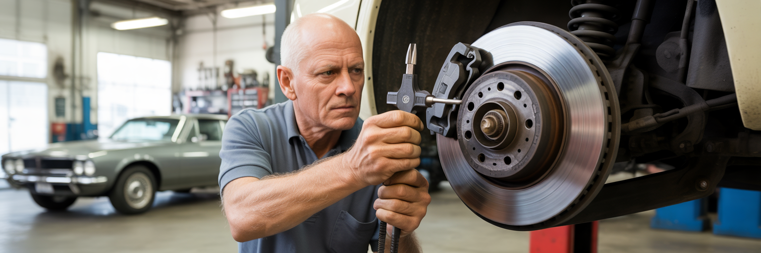
Cast iron rotors do not last forever, and automakers leave no guesswork regarding when the metal reaches the end of its functional life. Every factory and aftermarket rotor carries a minimum brake rotor thickness specification stamped or cast directly into the metal. If you wire-brush the dirty center hat around the wheel studs or inspect the outer perimeter edge of the cooling vanes, you will find an alphanumeric stamping such as MIN THICK 26.0 MM or MIN THK 1.024 IN.
Understanding these markings requires distinguishing between three separate engineering specs. The nominal thickness is the measurement of a brand-new rotor straight out of the box. The machine-to thickness is the lowest allowable measurement a technician can cut the rotor down to on a lathe while still leaving enough iron to survive a full set of new brake pads. Finally, the discard thickness is the absolute floor where the rotor must be removed from service immediately.
Running a rotor below its minimum specification creates severe physical and thermal hazards. As the friction plates wear thinner, the rotor loses the physical mass required to absorb heat. During hard stops or long mountain descents, an underweight disc saturates with heat almost instantly, boiling the brake fluid in the caliper and causing dangerous pedal fade. Worse yet, an overly thin rotor forces the hydraulic caliper pistons to extend too far out of their bores, increasing the risk of piston cocking, fluid leaks, or the cast iron friction ring cracking completely away from the center hat.
How to Measure a Rotor Accurately With an Outside Micrometer
Eyeballing a rotor from across the garage bay tells you almost nothing about its remaining mass. Even reaching for a standard digital slide caliper or Vernier caliper often produces a false sense of security. As brake pads wear into the iron face over tens of thousands of miles, they leave behind a slightly recessed track bordered by an untouched, rusty outer lip along the very edge of the disc. Because standard slide calipers have long, flat jaws, placing them over the edge of the rotor causes the jaws to bridge across that raised outer rust lip, yielding a falsely high thickness reading.
Accurate evaluation requires a calibrated outside micrometer or a specialized brake rotor caliper equipped with pointed anvil jaws that clear the outer ridge. To check the disc properly, wipe the swept surface clean and position the micrometer anvils roughly half an inch inward from the outer perimeter edge, squarely in the center of the pad wear path. Take measurements at six to eight evenly spaced clock positions around the perimeter of the rotor. Recording multiple points ensures you find the thinnest section of the iron ring rather than relying on a single spot.
The Gray Area of Remaining Metal for the Next Pad Cycle
The trickiest decision during a brake inspection happens when your micrometer reading lands just barely above the stamped minimum specification. Suppose your crossover front rotor has a nominal new thickness of 28.0 millimeters, a stamped discard limit of 26.0 millimeters, and your micrometer reads 26.4 millimeters today. Technically, that rotor is above the legal discard number right now.
However, approving that rotor for another round of service is a classic mistake. A fresh set of brake pads will easily wear away another 1.0 to 1.5 millimeters (0.040 to 0.060 inches) of cast iron over the next 40,000 miles of driving. Reusing a rotor that only has 0.4 millimeters of usable metal remaining guarantees the disc will drop well below its safe structural floor halfway through the life of the new pads. Comparing your exact micrometer readings against the typical wear allowances in the table below gives you an objective pass or fail metric before buying parts.
Typical Brake Rotor Thickness Ranges and Thermal Wear Thresholds by Vehicle Class
| Vehicle Segment | Nominal New Thickness | Typical Minimum Spec | Maximum Safe Wear Allowance | Primary Low Thickness Risk |
|---|---|---|---|---|
| Compact Passenger Car (Front Vented) | 24.0 mm to 26.0 mm | 22.0 mm to 24.0 mm | 2.0 mm (0.078 in) | Rapid thermal saturation and pedal fade in city traffic |
| Midsize Crossover SUV (Front Vented) | 28.0 mm to 30.0 mm | 26.0 mm to 28.0 mm | 2.0 mm (0.078 in) | Caliper piston overextension and fluid boiling on grades |
| Half Ton Pickup Truck (Front Vented) | 32.0 mm to 34.0 mm | 30.0 mm to 31.5 mm | 2.0 mm to 2.5 mm (0.098 in) | Heat checking and structural cracking under trailer loads |
| Passenger Car or Light SUV (Rear Solid) | 10.0 mm to 12.0 mm | 8.5 mm to 10.0 mm | 1.5 mm to 2.0 mm (0.059 in) | Mechanical warping and pad backing plate wedging |
These specifications represent standard OEM engineering tolerances across common North American passenger vehicles and light trucks. Always verify the exact stamped specification on your specific rotor hat or factory service manual before making a replacement decision.
Identifying Surface Damage Scoring Rust and Heat Spots
Deep Radial Grooves and the Fingernail Test
A brake rotor can pass a micrometer thickness test with plenty of iron to spare and still fail a visual inspection due to surface damage. Recognizing the physical signs of bad brake rotors starts with looking closely at the concentric circles etched into the swept face. Minor, hair-thin swirl lines are normal byproducts of friction, especially on trucks or sedans running aggressive semi-metallic pads. Deep radial scoring, on the other hand, happens when coarse road grit gets trapped between the pad and disc, or when a neglected brake pad wears completely through its friction material and grinds its steel backing plate into the rotor.
Weekend mechanics can evaluate these grooves quickly using the fingernail test. With the wheel removed and the rotor completely cool to the touch, drag the tip of your fingernail perpendicularly across the friction ring from the inner hat outward to the edge. If your nail glides across faint waves without snagging, the surface texture is acceptable. If your fingernail catches sharply in deep ridges or valleys exceeding roughly 0.015 to 0.030 inches in depth, the surface is too compromised to pair with fresh flat brake pads.
Flash Rust Versus Structural Salt Belt Corrosion
Evaluating rust on cast iron requires separating harmless cosmetic oxidation from destructive structural rot. Because brake rotor friction rings must remain bare, unpainted cast iron to generate proper friction, they oxidize almost immediately when exposed to moisture. If you wash your car on a Sunday afternoon or leave it parked outside during a humid rainstorm, a bright orange layer of flash rust will coat the discs by Monday morning. That superficial film wipes off cleanly during your first two brake applications at the end of the street and poses zero threat to braking performance.
Drivers in northern snow-belt states like Michigan, Ohio, and New York face a far more destructive enemy. Months of exposure to liquid calcium chloride brine and rock salt attack the rotor from the edges and inside the internal cooling channels, a harsh reality we detail in our look at why some high-mileage cars age better than others. Structural corrosion forms thick, flaky ridges of dark scale that creep inward from the outer perimeter and outward from the center hat, shrinking the shiny swept track where the pad actually touches the metal. Even worse, salt rot often eats away the hidden inboard face of the rotor (the side facing the suspension knuckle) while the visible outboard face behind the alloy wheel spokes still looks clean. When rust scale pits the friction ring or clogs the internal cooling vanes between the two rotor plates, the disc loses its ability to shed heat and must be discarded.
Blue Heat Spots Martensite Hardening and Thermal Cracking
Extreme heat leaves unmistakable metallurgical fingerprints on cast iron. If a driver rides the brakes down a steep pass, or if a sticking caliper slide pin prevents a pad from releasing fully on the highway, rotor surface temperatures can spike past 1,200 degrees Fahrenheit. This thermal abuse creates dark bluish-purple rainbow smudges or leopard-like blotches scattered across the friction ring.
Those dark blotches are more than cosmetic stains. Intense localized heat alters the crystalline structure of the pearlitic cast iron, transforming small patches of the metal into a super-hard metallurgical phase known as cementite or martensite. Because these hardened martensite islands resist wear much more stubbornly than the softer cast iron surrounding them, the rotor begins to wear unevenly over subsequent miles, creating raised bumps that hammer against the caliper piston every time you slow down. Thermal stress can also produce fine hairline surface crazing or deep structural thermal cracks. When inspecting your brakes, run through these seven visual checkpoints to separate minor blemishes from terminal defects:
- Fingernail-catching radial grooves carved deeper than 0.015 inches into either the outboard or inboard friction face.
- Flaky dark rust creep encroaching inward from the outer perimeter lip or center hat, narrowing the shiny pad contact band.
- Deeply pitted corrosion craters scattered across the swept surface that fail to clear up after several normal highway stops.
- Clogged or delaminating internal cooling vanes around the rotor perimeter that restrict airflow between the two friction plates.
- Bluish-purple thermal discoloration bands or dark circular leopard spots indicating localized martensite hardening.
- Fine spiderweb heat checking that has grown into a continuous macro-crack reaching the outer edge or inner rotor hat.
- A raised outer perimeter rust ridge exceeding 1 millimeter in height on both sides, signaling advanced wear across the main friction track.
Measuring Lateral Runout and Disc Thickness Variation
Debunking the Warped Rotor Myth
Walk into almost any repair shop waiting room and tell the service counter that your steering wheel shakes when braking at highway speeds, and you will likely hear that you have warped rotors. Despite how frequently that phrase gets repeated by mechanics and drivers alike, true thermal warping of a street brake rotor is largely a myth. Cast iron is remarkably rigid and requires furnace temperatures approaching 2,000 degrees Fahrenheit to physically soften and twist like a wet plank of wood left in the sun.
In almost every street car scenario, that annoying steering wheel shimmy and rhythmic brake pedal pulsation stem from two distinct mechanical issues: lateral runout and Disc Thickness Variation (DTV). When diagnosing front-end shakes, separating brake pulsation from worn tie rods, ball joints, or wheel bearings is essential, which is why we recommend reviewing our troubleshooting guide on why a car makes a clunking noise when turning the steering wheel if the vibration occurs even when your foot is completely off the brake pedal.
How Lateral Runout Creates Disc Thickness Variation
Lateral runout measures how much a brake rotor wobbles side to side as it spins on the wheel hub. No mechanical assembly is flawless, so automakers establish a strict brake rotor runout limit, typically between 0.002 and 0.004 inches (0.05 to 0.10 millimeters), depending on the vehicle platform. When a rotor spins with less than 0.002 inches of wobble, it tracks smoothly between the caliper pads.
When lateral runout exceeds that tight threshold, a slow, destructive chain reaction begins. As you cruise down the interstate at 70 miles per hour with your foot off the brake pedal, the high spot on the wobbling rotor brushes lightly against the outboard brake pad once per revolution, while the opposite side of the rotor brushes the inboard pad half a turn later. You will never feel or hear this microscopic contact while driving. However, after 3,000 to 5,000 miles of continuous highway rotation, that constant light brushing wears two opposite locations on the rotor face slightly thinner than the rest of the disc.
This uneven wear pattern is called Disc Thickness Variation. Once the thickness difference between the thick and thin spots on the iron ring reaches just 0.0005 to 0.001 inches (less than a third of the thickness of a human hair), the brake pads can no longer glide over the surface smoothly. When you step on the brake pedal, the caliper pistons are rapidly forced inward and outward as the thick and thin sections pass through the caliper jaws, pumping hydraulic fluid back up the brake lines and shaking the pedal beneath your foot.
Checking Runout With a Dial Indicator and Cleaning the Hub Flange
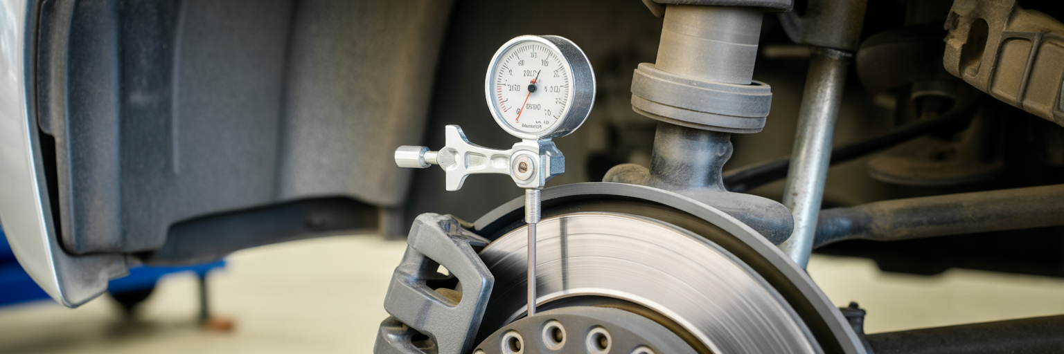
Verifying whether a rotor spins true requires a magnetic-base dial indicator. After removing the wheel, thread all the lug nuts back onto the studs backwards (flat side against the rotor hat) and torque them evenly to lock the rotor firmly against the wheel bearing hub, just as it sits when the wheel is mounted. Clamp the dial indicator base securely to the cast iron steering knuckle, position the measuring stylus tip about half an inch inside the outer edge of the rotor face at a 90-degree angle, and zero the gauge. Slowly rotating the hub two full turns by hand reveals the total indicated runout on the dial needle.
Here is the critical detail that catches many novice DIYers off guard: excessive runout is frequently caused by the wheel hub underneath the rotor rather than the rotor itself. Over years of winter driving, rust scale and corrosion flakes build up on the steel wheel bearing hub flange where the back of the rotor sits. If you pull off an old rotor and slap a brand-new rotor directly over a crusty, uncleaned hub flange, a tiny 0.002-inch flake of rust trapped near the center wheel studs gets magnified by geometry across the wide diameter of the disc. That microscopic rust flake at the center translates into 0.006 inches of wobble at the outer edge of the brand-new rotor, triggering fresh DTV and pedal pulsation within a few months.
Why New Brake Pads Perform Poorly on Compromised Rotors
Contact Patch Geometry Mismatch and Extended Stopping Distances
To understand why installing fresh pads over worn, unmachined rotors causes immediate drivability issues, picture pressing a brand-new, perfectly flat wooden sanding block against an old corrugated metal washboard. The flat block cannot touch the bottoms of the grooves. Instead, it rests entirely on the narrow, raised ridges of the washboard.
The exact same geometric mismatch happens inside your brake caliper during a hasty pad slap. Brand-new brake pads come out of the box machined completely flat. An old rotor that has already worn through a set of pads is never truly flat; it features concentric microscopic peaks and valleys, a slightly dished or concave wear profile across the face, and a raised rust lip at the inner and outer edges. When hydraulic pressure clamps the flat new pad against the contoured old disc, the friction material only contacts the high peaks of the old iron. This mismatch reduces the effective friction contact patch by 30 to 50 percent during the first several hundred miles of driving, resulting in a soft, spongy brake pedal and noticeably longer stopping distances during sudden highway slowdowns.
Disrupted Transfer Layers and Bedding Failure
Automotive braking relies on far more than raw mechanical scraping. Modern semi-metallic and ceramic brake pads operate through a combination of abrasive friction (the physical rubbing of the pad against the cast iron) and adherent friction. Adherent friction depends on a process called bedding or burnishing, where controlled heat bakes an ultra-thin, uniform molecular transfer layer of pad resin into the microscopic pores of the cast iron rotor. Once laid down properly, the brake pad actually grips a sacrificial film of its own material bonded to the spinning disc, which we explain step by step in our DIY guide on how to bed in brake pads after an installation.
When you press a new pad against an old rotor that is already glazed, grooved, or coated with patchy residue from a different brand or chemical formulation of brake pad, the burnishing process breaks down completely. Because only the narrow high ridges of the old rotor touch the flat new pad, all the kinetic energy concentrates onto tiny stripes of the new friction material. Those narrow contact stripes overheat instantly, scorching and glazing the fresh binding resins before the rest of the pad face even makes contact. As highlighted in a technical bulletin from OEM brake manufacturer ADVICS, improper surface preparation and uneven transfer layer buildup directly cause erratic grab-and-release friction, thermal judder, and premature wear.
High Frequency Harmonics Squealing and Tapered Pad Wear
Beyond compromised stopping power, mating flat pads to rough or lipped rotors is the single leading cause of embarrassing brake noise. Brake squeal is not simply the sound of two smooth surfaces sliding past each other; it is a high-frequency harmonic vibration ranging between 1,000 and 15,000 Hertz. When the square outer edge of a fresh brake pad rides up onto the raised outer rust lip of an old rotor, the pad cannot sit flush against the caliper piston. Instead, the pad tilts slightly and chatters across the uneven iron ridges like a fingernail skipping across a chalkboard, turning the heavy iron rotor into a ringing bell at every stoplight.
Even worse, switching pad compounds without replacing or machining the rotor invites chemical cross-contamination. If your vehicle previously wore semi-metallic pads and you upgrade to low-dust ceramic pads on the untouched old rotors, the residual metallic transfer layer left on the iron interferes with the new ceramic polymers. Ultimately, trying to save a hundred dollars by skipping rotor replacement often backfires by carving deep matching grooves into your brand-new pads, forcing you to buy a second set of pads along with new rotors just to stop the noise.
Resurfacing Old Rotors Versus Buying New Replacements
How Off Car and On Car Brake Lathes Restore the Friction Surface
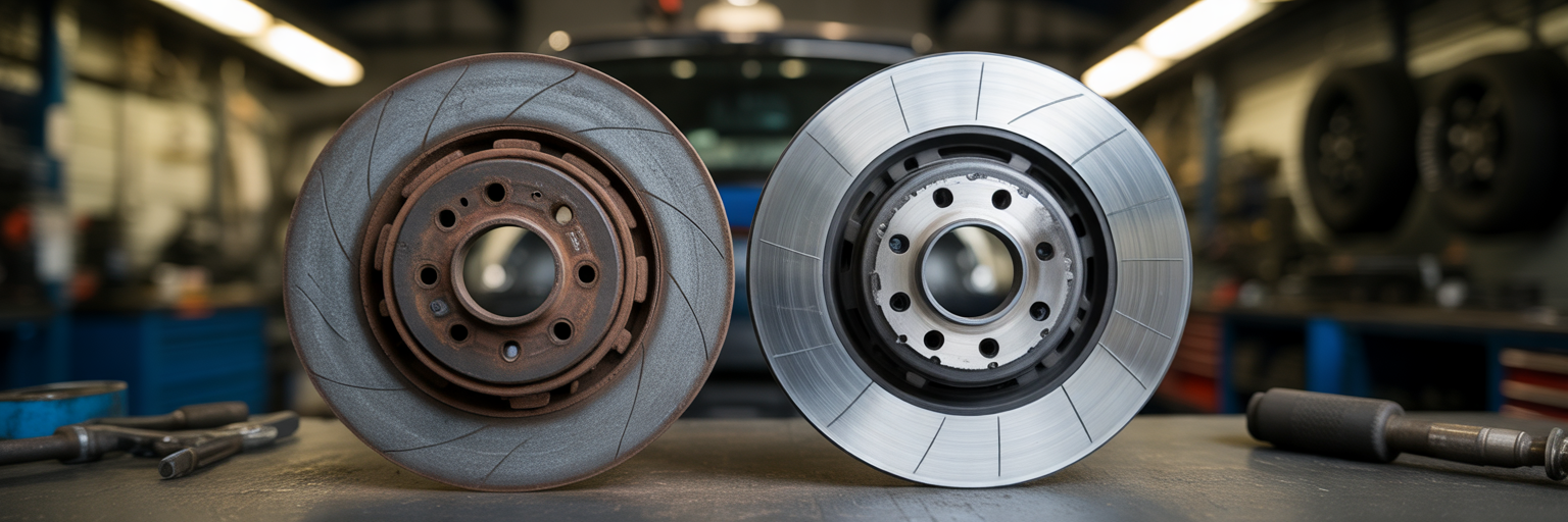
When weighing whether to resurface vs replace brake rotors, it helps to understand what resurfacing actually accomplishes. Resurfacing, commonly referred to in the garage as turning or machining rotors, uses a precision machine lathe equipped with twin carbide cutting bits to shave a thin layer of cast iron (typically 0.004 to 0.015 inches total) off both friction faces simultaneously. An off-car bench lathe spins the removed rotor on a centered arbor shaft, cutting away radial grooves, minor rust pitting, old pad transfer layers, and DTV thickness variations before finishing with a non-directional crosshatch swirl pattern.
Some dealerships and specialty shops also utilize on-car brake lathes. Rather than removing the rotor and mounting it on a workbench, the technician bolts the lathe mechanism directly to the vehicle’s caliper mounting bracket and spins the vehicle’s own wheel hub. Machining the disc while it is bolted to the car offers a distinct engineering advantage: it cuts the rotor faces perfectly parallel to that specific vehicle’s wheel bearing, automatically canceling out any minor lateral runout present in the hub flange itself.
The Modern US Shop Economics of Labor Rates Versus New Coated Rotors
Despite the mechanical elegance of a precision lathe cut, rotor turning has largely disappeared from everyday passenger car repairs across the United States. The reason comes down to simple shop mathematics and modern parts supply chains. Operating a brake lathe is not a fast process; clamping the rotor, setting up vibration-dampening belts, taking a rough cut, and running a slow finishing pass takes a skilled technician 30 to 45 minutes per axle. With average independent repair shop and dealership labor rates sitting between $120 and $180 per hour across most US metro areas, paying a mechanic to machine two rotors easily costs $60 to $120 in labor alone.
Meanwhile, global manufacturing has driven the price of brand-new aftermarket rotors down dramatically. For mainstream daily drivers like a Honda CR-V, Toyota Camry, or Ford F-150, high-quality replacement rotors treated with factory zinc or Geomet polymer anti-rust coatings on the center hat and cooling vanes frequently retail between $45 and $90 apiece. For roughly the same out-of-pocket cost as lathe labor, the car owner receives brand-new components with 100 percent of their original factory thermal mass and corrosion protection intact.
When Machining Existing Rotors Still Makes Financial Sense
While buying new iron is the smartest default choice for most compact sedans and crossovers, resurfacing still holds a valuable place in specific automotive segments. Three-quarter-ton and one-ton heavy-duty pickup trucks, commercial delivery vans, and dedicated tow rigs often feature massive, thick-cast rotors that cost over $180 each and carry plenty of excess iron to tolerate a lathe pass, a maintenance reality familiar to drivers researching our picks for the best used trucks for towing a camper. Similarly, older trucks equipped with captive hub-over-rotor designs require pressing out wheel bearings or removing ABS tone rings just to separate the rotor from the hub, making an on-car lathe pass far more efficient than full replacement. High-performance sports cars equipped with expensive two-piece floating aluminum-hat rotors costing $400 to $900 per corner are also prime candidates for careful machining, provided they measure well above their stamped machine-to threshold. The comparison matrix below breaks down how these two approaches stack up for everyday car owners.
Decision Matrix Comparing Rotor Resurfacing and Full Rotor Replacement
| Evaluation Factor | Resurfacing Existing Rotors | Installing New Replacement Rotors | Practical Impact for Car Owners |
|---|---|---|---|
| Typical Cost per Axle (US Market) | $50 to $110 in machine labor | $90 to $220 for quality coated parts | Price gap is often under $60 total per axle |
| Thermal Mass and Heat Capacity | Reduced by 0.010 to 0.030 inches of shaved iron | Restored to 100 percent factory nominal thickness | New rotors resist highway brake fade much better |
| Corrosion Protection | Bare iron exposed on machined edges | Factory zinc or Geomet polymer coatings on hats and vanes | Coated new rotors prevent unsightly wheel hub rust |
| Hub Runout Correction | On car lathe matches rotor exactly to hub flange | Requires thorough wire brush hub cleaning before mounting | On car turning fixes minor hub bearing flange runout |
| Ideal Vehicle Application | Heavy duty trucks and expensive OEM two piece discs | Daily driver sedans, crossovers, and salt belt vehicles | Most daily drivers benefit more from brand new metal |
Cost estimates reflect typical US independent repair shop labor rates and retail aftermarket parts pricing for mainstream passenger vehicles. Luxury, European, and heavy-duty truck components carry higher parts costs.
Questions to Ask When a Shop Recommends Pads and Rotors
Requesting Exact Micrometer and Runout Numbers Over Vague Opinions
Receiving a phone call from a service advisor stating that your brake job just jumped by $350 because you need new rotors can feel frustrating, especially if your brakes were not pulsating when you dropped the car off. Many national chain stores and dealership service departments operate under a blanket policy of quoting new rotors with every single brake pad replacement. From the shop’s perspective, bundling new rotors eliminates the risk of an angry customer returning two weeks later complaining that their new pads are squealing against old, lipped discs.
While installing fresh rotors alongside new pads is frequently the right technical call on modern thin-rotor vehicles, you should never have to accept vague phrases like your rotors look a little grooved or we always do them together. Reputable technicians take objective measurements during their inspection and are happy to share the hard numbers. Before authorizing the extra expense on your repair estimate, ask your service advisor or mechanic these six specific questions:
- What did my current rotors measure on the micrometer in millimeters or thousandths of an inch, and what is the stamped minimum discard specification on the rotor hat?
- If the rotors are still above minimum thickness, is there enough usable metal left above the machine-to spec to survive another full set of brake pads without dropping below the discard limit?
- Which specific surface defect disqualified the rotors from reuse: deep radial scoring, inboard rust scale creep, bluish thermal hard spots, or Disc Thickness Variation?
- Can you text me a digital inspection photo showing the inboard rotor face and the micrometer gauge reading, or walk me out to the lift to show me the condition of the friction rings?
- Are the replacement rotors you are quoting coated with a zinc or Geomet anti-corrosion finish on the center hat and cooling vanes so they will not rust out prematurely next winter?
- Does your brake service procedure include cleaning the wheel bearing hub flange to bare metal, checking installed lateral runout, and torquing the wheel lug nuts by hand with a calibrated torque wrench?
Verifying Proper Hub Preparation and Lug Nut Torque Procedures
That final question on the list is just as important as the price of the parts. Buying top-tier rotors will not save you from a vibrating steering wheel if the technician rushes the installation in the bay. As noted in the technical troubleshooting documentation from Ferodo Brakes, improper mounting surface preparation and uneven wheel fastener clamping torque are primary root causes of premature lateral runout and DTV on newly installed brake components.
When a conscientious technician installs a new rotor, they first use a rotary bristle disc or wire brush to scrub all rust scale off the wheel hub flange around the studs, ensuring the new rotor hat sits dead flat against bare steel. Just as critical is how the wheels are reinstalled at the end of the job. If a hurried mechanic blasts the lug nuts tight in a circle using an unregulated pneumatic impact wrench delivering 250 foot-pounds of torque, the uneven clamping force physically distorts the thin center hat of the new rotor and pulls the friction ring out of alignment. Insisting on a shop that tightens lug nuts in a cris-crossing star pattern with a calibrated hand torque wrench ensures your new pads and rotors deliver smooth, silent, and dependable stopping power for tens of thousands of miles to come.